Design Process
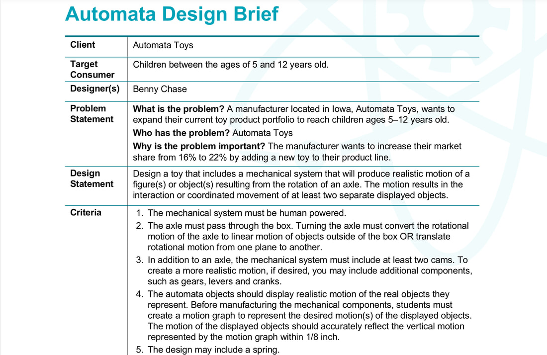
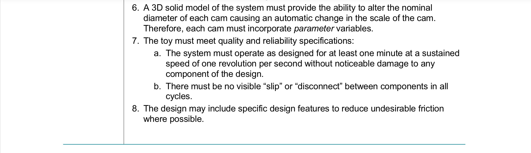
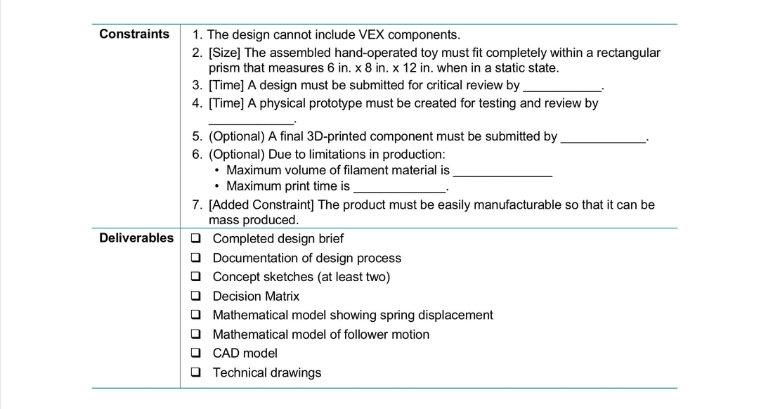
Define a Problem
Generate Concepts
Brainstorming list:
* Aircraft where parts move, including propellor through automata movement
* Airplane that rolls/tips left to right as if turning
* An airplane taking off/landing
* A robotic arm that moves
* A robotic hand where the fingers move
* A machine that turns itself off using a motor to stop the power (I have seen these before, it can be a bit tricky to make)
* An airplane where the parts (elevator, rudder, ailerons) move but the propellor is spun using a small motor, making it easier to make (economy, Occam's Razor)
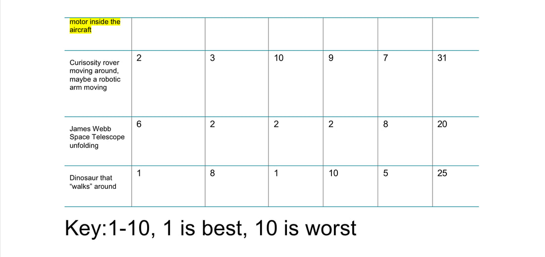
* Curiosity rover moving around
* James Webb Space Telescope unfolding the mirror
* Dinosaur (Maybe T-Rex or velociraptor) that "walks"
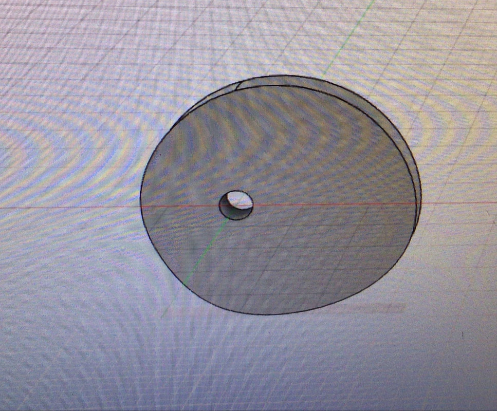
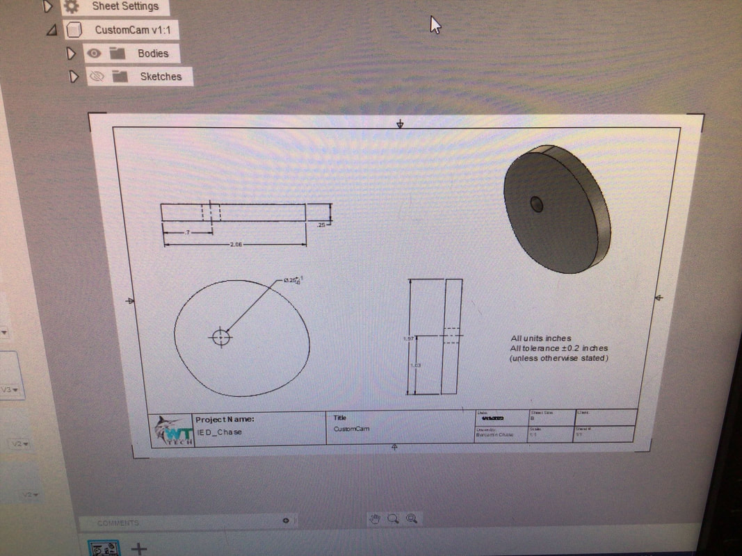
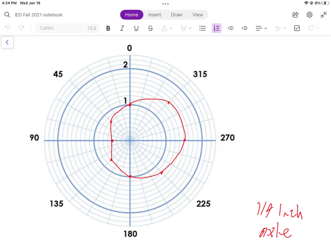
Reason for using the custom cam:
The custom cam pictured above will give the model a very smooth motion with a large displacement range.
It will make the follower move slowly and smoothly up and down, resulting in a very controllable, fluid motion.
It will create less friction with the follower than a more jagged, steep cam.
This will reduce failure and problems in the design due to friction.
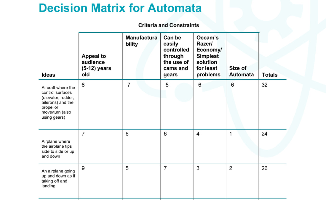
Justification for the selected design:
I chose to design an aircraft that has moving control surfaces for multiple reasons.
There were a few criteria and constraints I considered such as appeal to a kid, manufacturability, ease of control (frictionless),
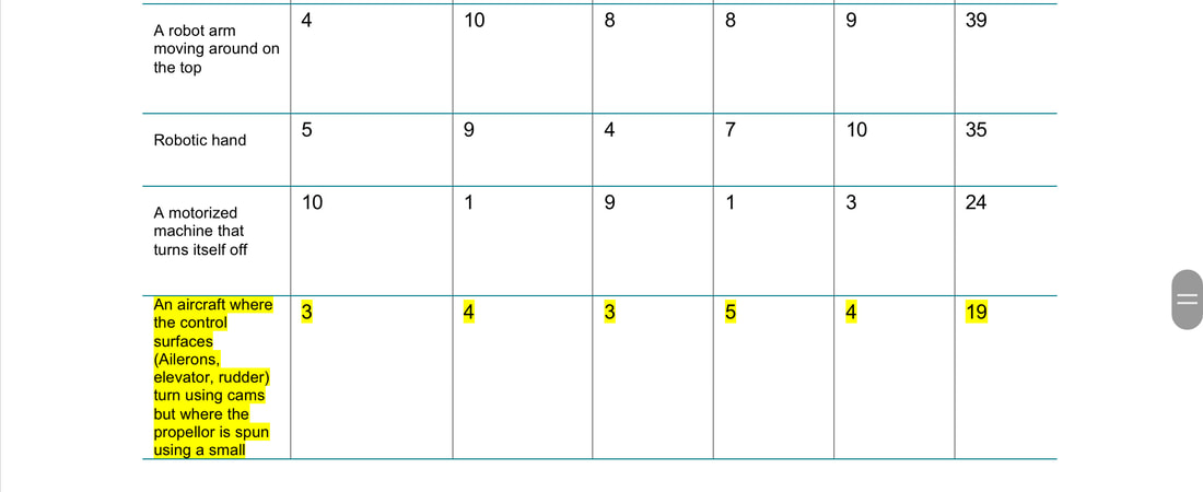
economy, and size. The aircraft with moving control surfaces design had the best score of 19 in the decision matrix.
Kids love airplanes, trust me (I always wanted to sit by the window in airplanes).
Except babies, but the audience is meant to be 5-12 years old, as described in the design brief.
It would be easier to manufacture since the airplane could be attached to the top of the box through glue,
while for example a walking T-Rex would only be attached to the followers instead of being partially attached directly to the box.
It would be easy to control the control surfaces through cams and gears since a follower could just push the surfaces and a hinge/joint
would let the surface move. For example, the ailerons would be controlled with a follower simply pushing on the bottom,
and gravity would keep them resting on the follower, making them go up and down. It was also a simpler solution than other design
ideas since a robotic hand was very hard to design, had many moving parts, and would be extremely hard to manufacture.
I decided to not have the propellor move through cams, but instead have it stationary or use a very small motor to spin the propellor.
For size, the airplane could be scaled down to fit inside the size constraint for the automata box, whereas other ideas would need to
be scaled down so much that some small parts would be challenging to manufacture and hard to see.
Overall, the aircraft design with moving control surfaces but a stationary propellor had the best score of 19.
Automata Design in Autodesk Fusion 360
There were a few problems with the rendering, I had to use lower quality since I only had 100 cloud credits, and somehow not the entire motion study/joint motion worked perfectly.
Conclusion
The ailerons move up and down. This may seem simple, but there are actually multiple components involved. First, there is an axle.
This axle uses a revolute joint to spin. Cams are fixed onto the axle using rigid joints.
The cams and followers convert the radial motion of the axle into linear motion in the follower.
The followers sit on top of the cam using a contact set to detect when the cam touches the follower.
But there is one problem: the follower does not move down, it only glides up.
In Fusion 360, there is no gravity. So I had to add a rest position on the slider joint that defined the movement of the follower.
This gave the follower a sort of "spring" effect where it would always bounce or spring back to the rest position.
Combined with the contact set, it made the follower follow the outer edge of the non-centric cam.
I used two non-centric cams for the ailerons facing in opposite directions since ailerons always move in opposite directions on a real airplane.
One moves up while the other moves down, and vice versa. I added revolute joints between the ailerons and the wing of the airplane.
Then, I defined rest positions on these revolute joints and added contact sets between the ailerons and the followers.
This added the same "spring" effect where the aileron would always touch the follower and could be pushed up with the follower.
It could be pulled down by the "spring" effect of the rest position.
Making the elevator was very similar to the process of making the ailerons.
I used sort of an extended double pear cam to give the elevator a more sudden movement that would make it rise and fall more quickly.
To make the most realistic motion, a noncentric cam would be used to provide smooth, slow movement. But here I wanted to try a different cam.
The axle uses a revolute joint to spin. The cam is fixed to the axle using a rigid joint so it does not move.
Then, like in the aileron construction, a contact set is made between the follower and the cam.
To simulate gravity, a rest position is defined in the slider joint of the follower.
At the elevator, another contact set is made between the elevator and the follower, and to simulate gravity a rest angle/position
is defined in the elevator's revolute joint. For the follower to sit on the cam and still come out of the top of the box at the correct location,
I had to extend the bottom of the follower, as seen in the Automata Elevator (middle) video.
The rudder differs from the previous processes. The axle still uses a revolute joint to spin, but instead of a cam and follower,
it uses gears and another axle. The gears were made using the Spur Gear addon, and were fixed to the axles using rigid joints.
To make the interlocking gears transfer motion to each other, I used motion link.
Up at the rudder, I used motion link to bind the radial motion of the rudder to the radial motion of the vertical axle.
This made the rudder spin vertically, just as in a normal airplane.
I used limit dimensions to restrict the motion of the rudder so it could only spin around 70 degrees total, about 35 degrees each direction.
Thanks to Leonardo Zeng at GrabCAD for the great Piper Cub J-3 design for the top of the automata!