Design Process
Define a Problem
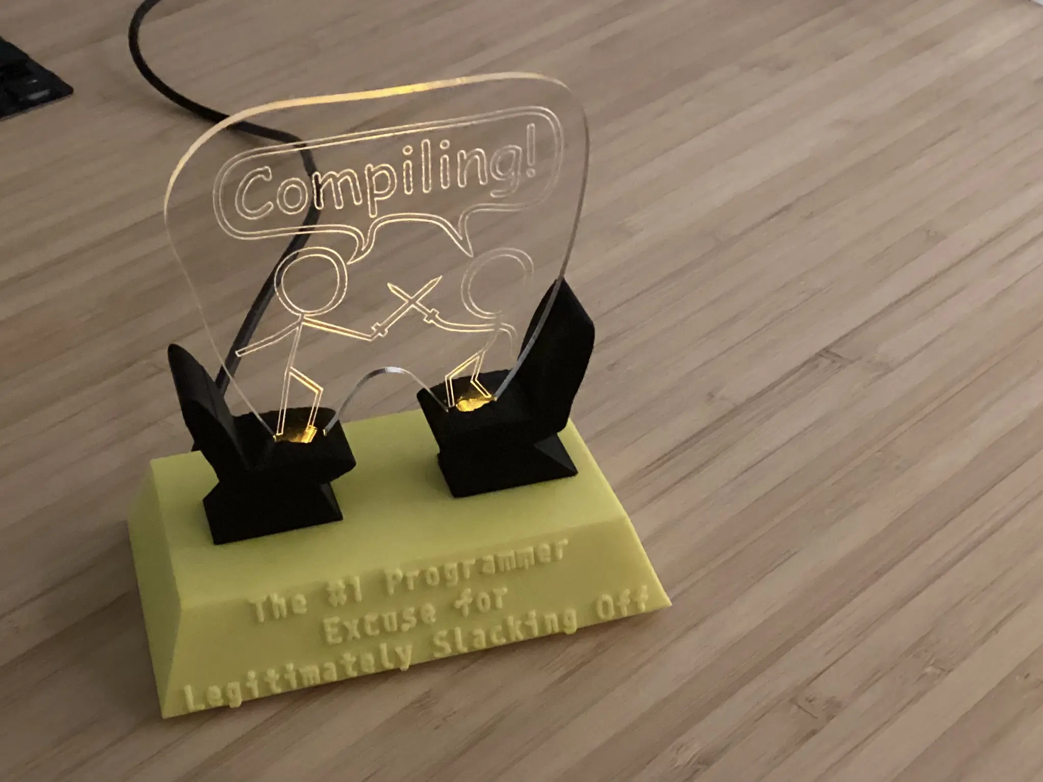
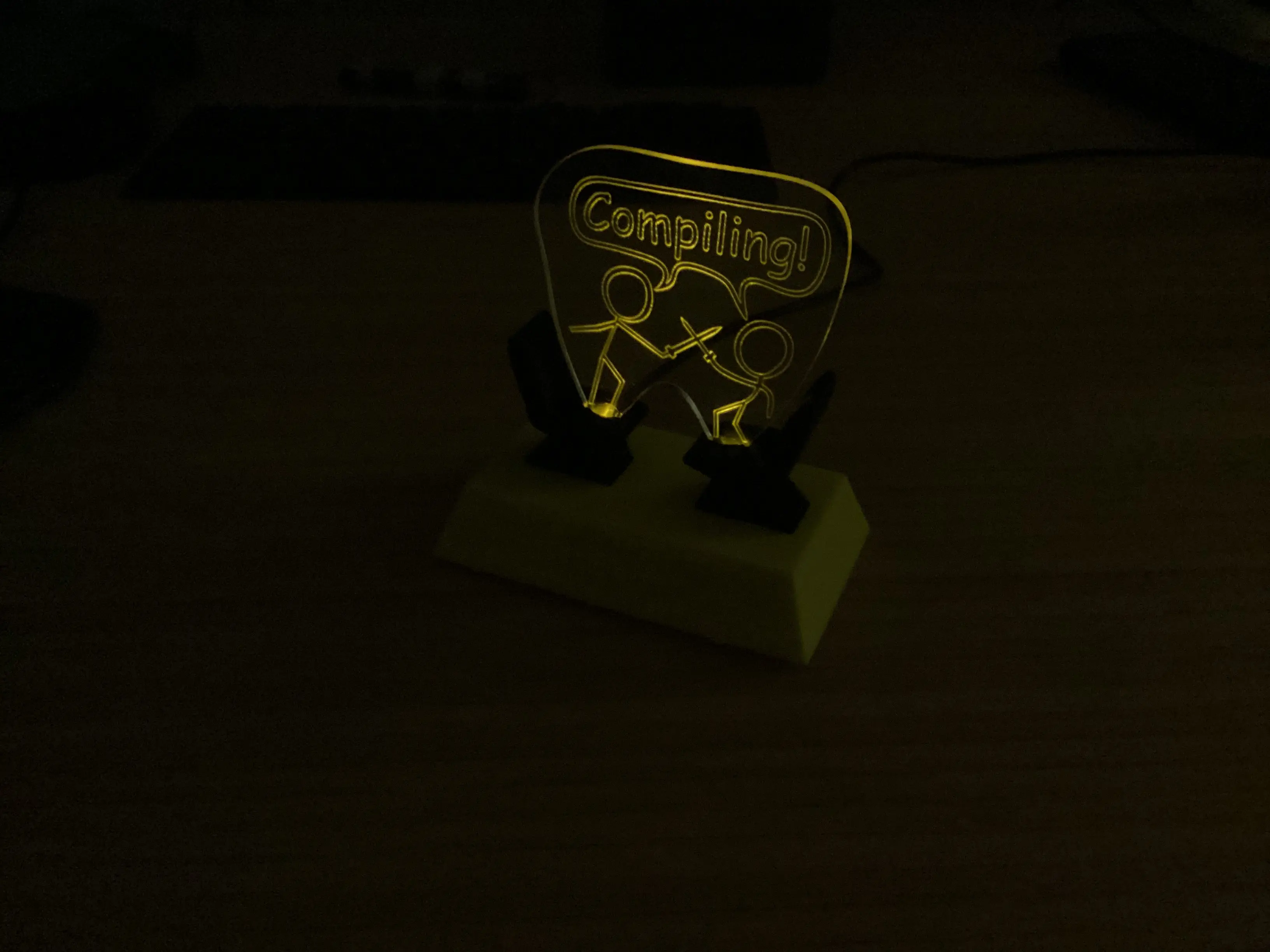
The goal of this project was to design and build a night light. This included designing and constructing a base, base cover to enclose electronics, and a piece of acrylic to act as a light diffuser. LEDs were used to shine light through the underside of a lasercut piece of acrylic. This would in turn diffuse the light emitted from the LEDs around a shape that was engraved, or cut partially through, the acrylic.
Generate Concepts
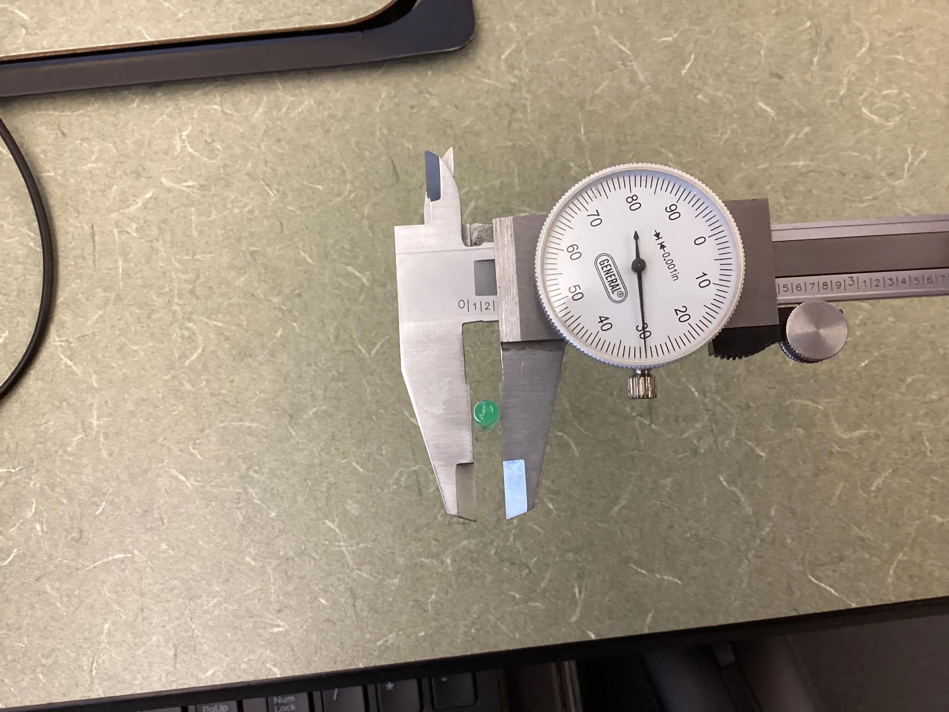
Before I could start designing the base of the night light, I needed to gather some measurements for reference and parts. A dial caliper is far superior for accurate and precise when taking small measurements than a ruler since it can measure to more decimal places, can be applied in many different measurement techniques (step, inset, inner diameter, outer diameter, length), and can be calibrated and zeroed. For example, the LEDs I used had a diameter of 0.2301 inches. On an imperial dial caliper, the large number represents whole inches, in this case 0 (not included in this measurement but visible further down the length of the caliper). Next, look for the smaller numbers along the main body of the dial caliper, in this case 2 (representing 0.2). These represent tenths of decimal inches. To find the hundredths of inches, look on the dial face and find the main marking behind the "hand," in this case 30 exactly (representing 0.030). When using scientific or engineering equipment, a standard measurement convention is to estimate to one more decimal place, in this case slightly past the 30 hundredths mark, so about 31 hundredths of an inch. This results in a measurement of 0.2301 inches for the diameter of the LED.
The "compiling" design was inspired by Randall Munroe's XKCD #303 (Available here).
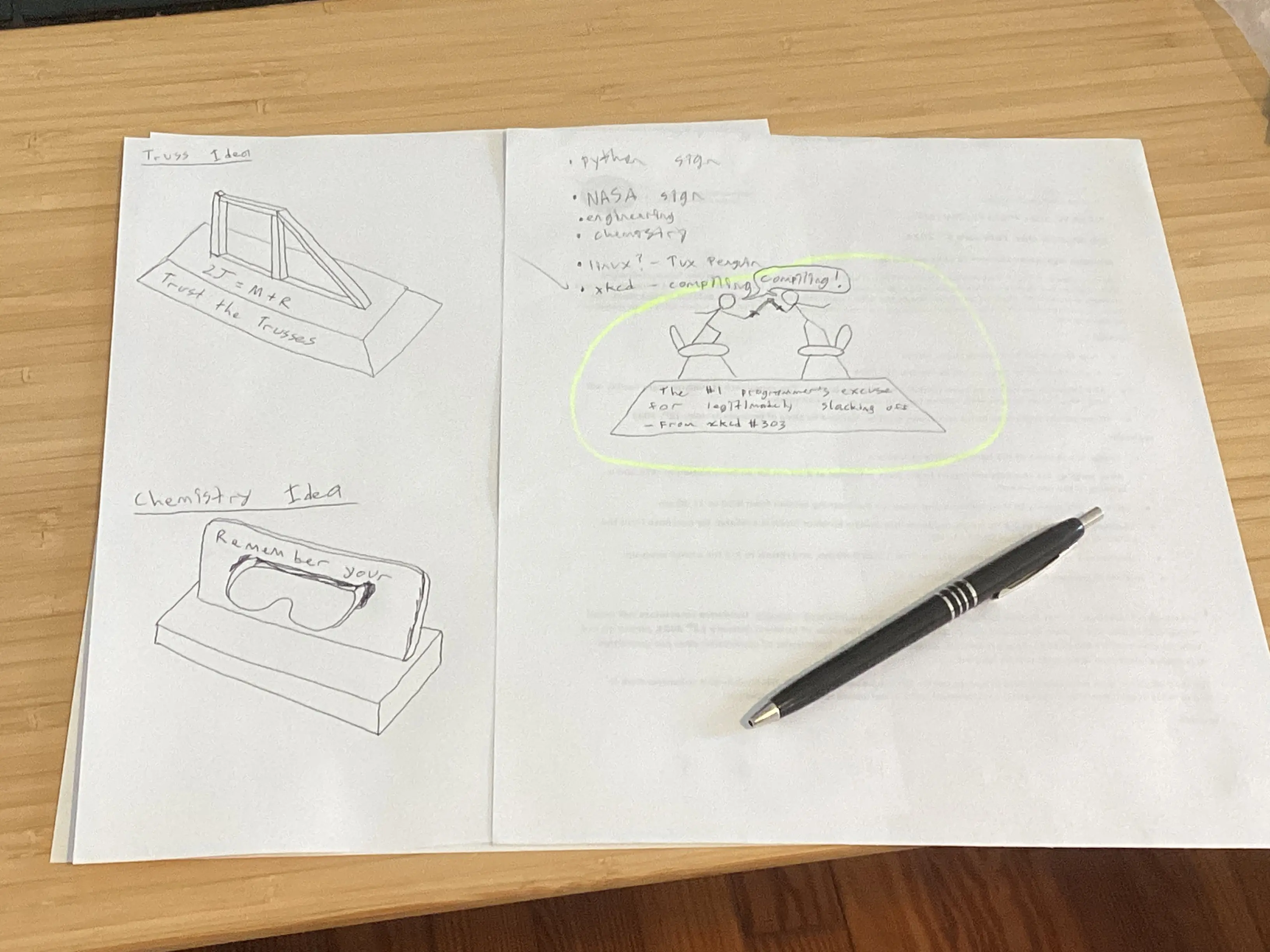
I chose to create the "compiling" design because it was funny, and would be a fun challenge. The idea to print the seats separately as a different color and mount the LEDs inside the seats worked quite well.
The other design ideas were more basic as asthetics would be concentrated mostly on the acrylic design and less on the case itself.
The "compiling" design differed from the other ideas I brainstormed due to the unique form of the electronics case.
Develop a Solution
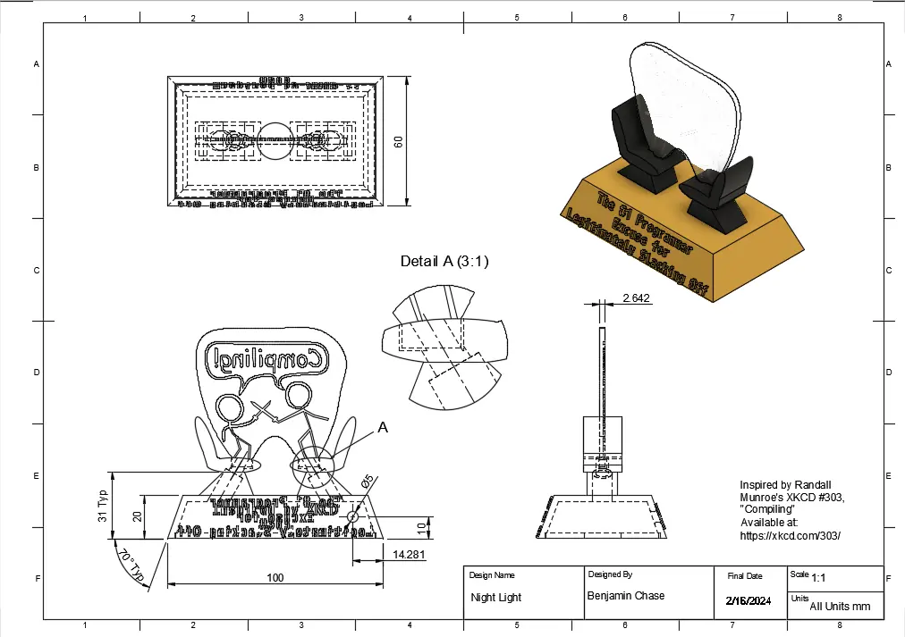
Above is a dimensioned engineering drawing of the base of the night light along with an interactive 3D model.

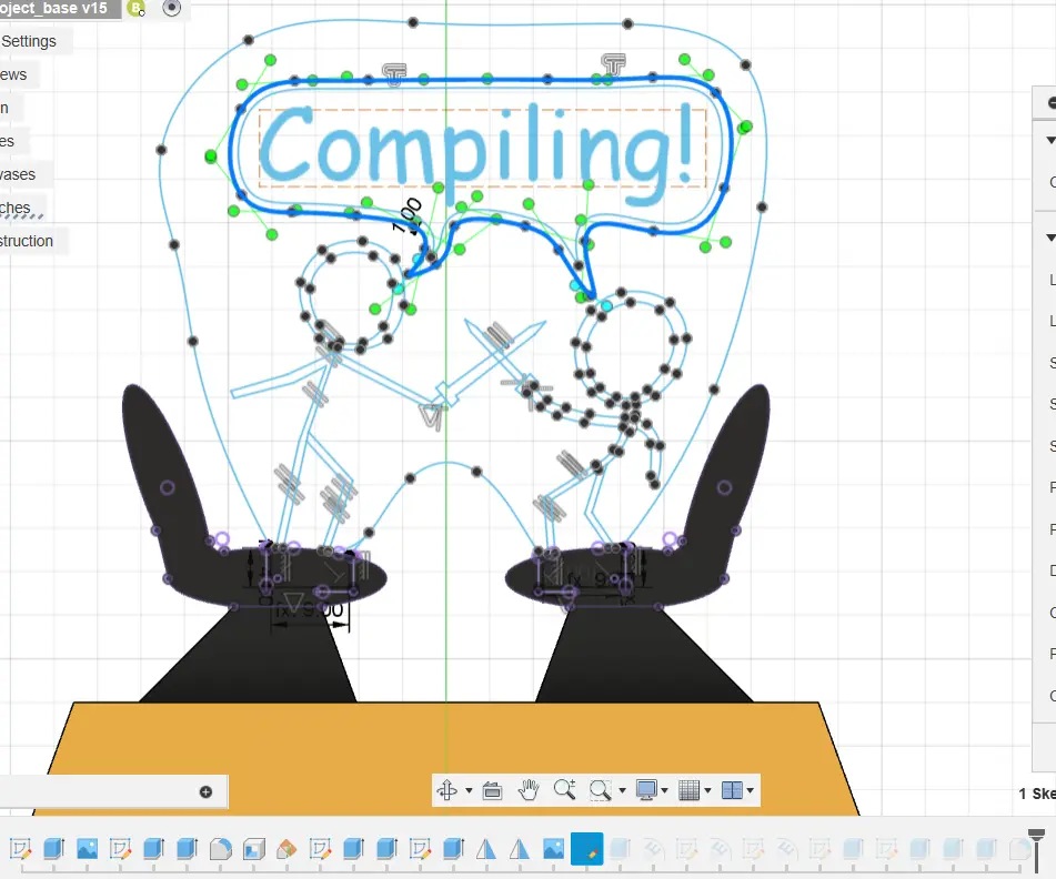
(First image) To begin with, I traced the comic from XKCD using splines and lines in Autodesk Fusion 360.
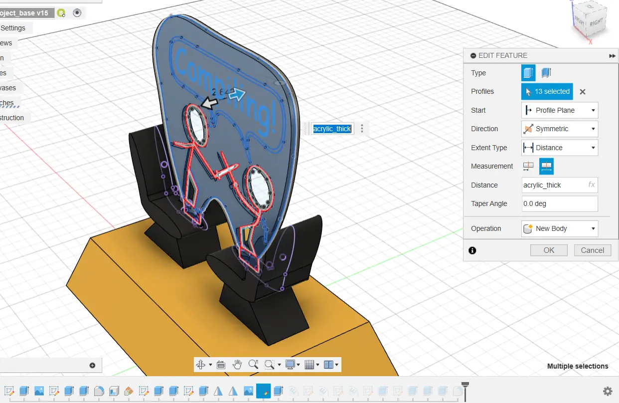
(Second image) Next, I made the 2D sketch into a 3D body by extruding it to the thickness of the acrylic.
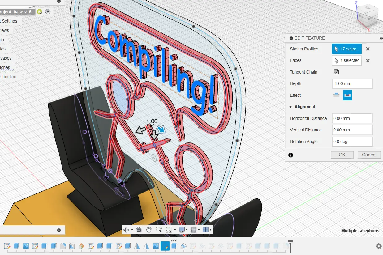
(Third image) Now that the basic acrylic shape was created, I could emboss (or engrave/etch) the characters into the acrylic.
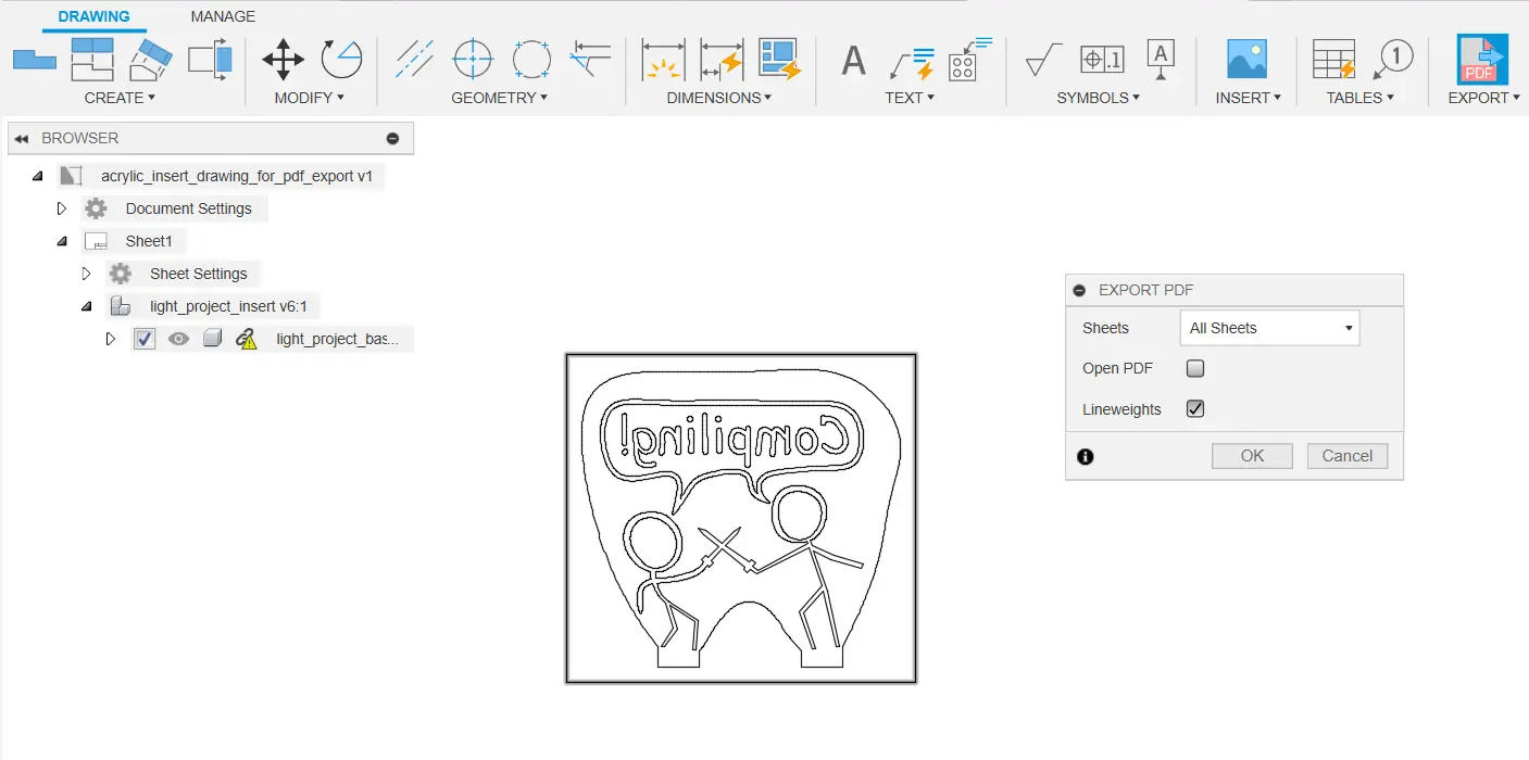
(Fourth image) To remove most double lines and keeps parts of the acrylic form together later, I created a drawing from the acrylic body in Fusion and exported it as a PDF.
Double lines are where overlaping lines are in a file more than once, and the lasercutter interprets this as two separate paths, thus travelling over the path twice. Double lines can result in a fire hazard, and absolutely must be removed!
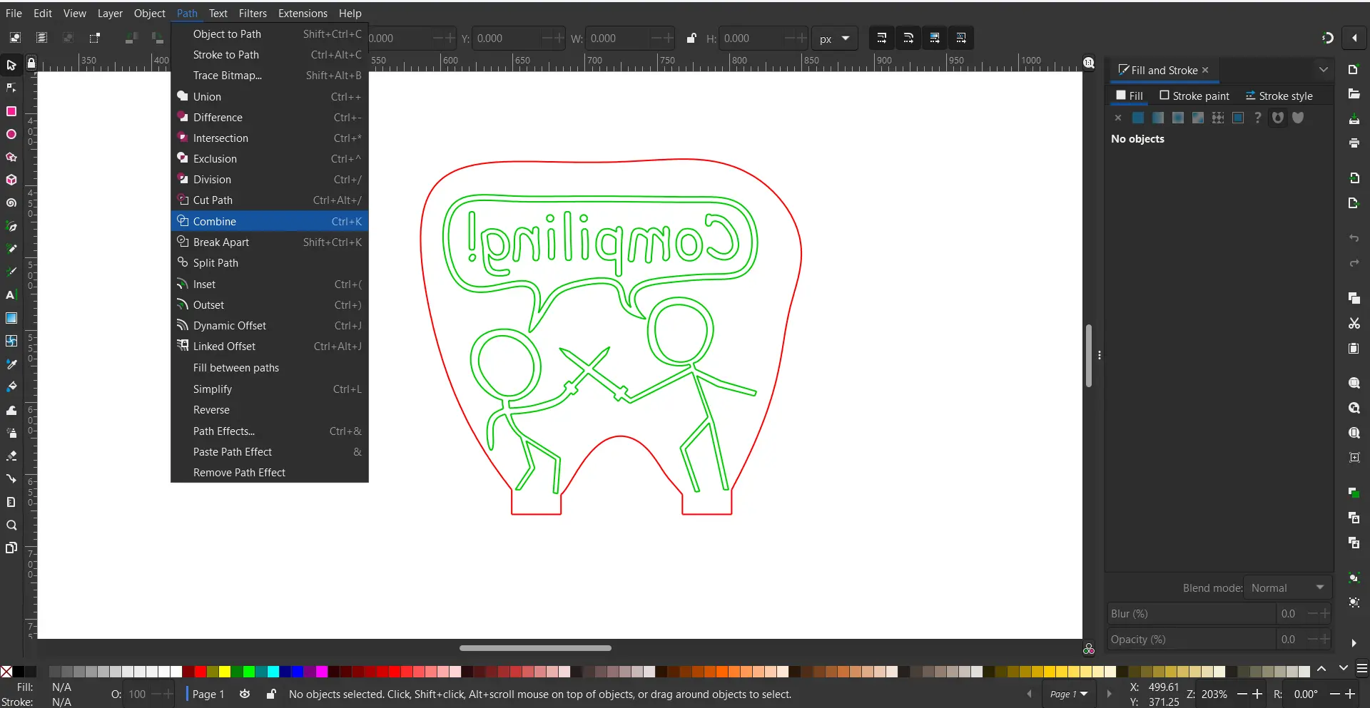
(Fifth image) I still had to check if any double lines remained and that all shapes were closed. To do this, I checked everything in Inkscape, an open-source graphic design software. From there, I made the outer edge a different color. The lasercutter interprets different colors as different functions, either cutting (going all the way through), scoring (going half way through), or engraving (like scoring an entire area, not just a line).
From there, I could export the file as an SVG.
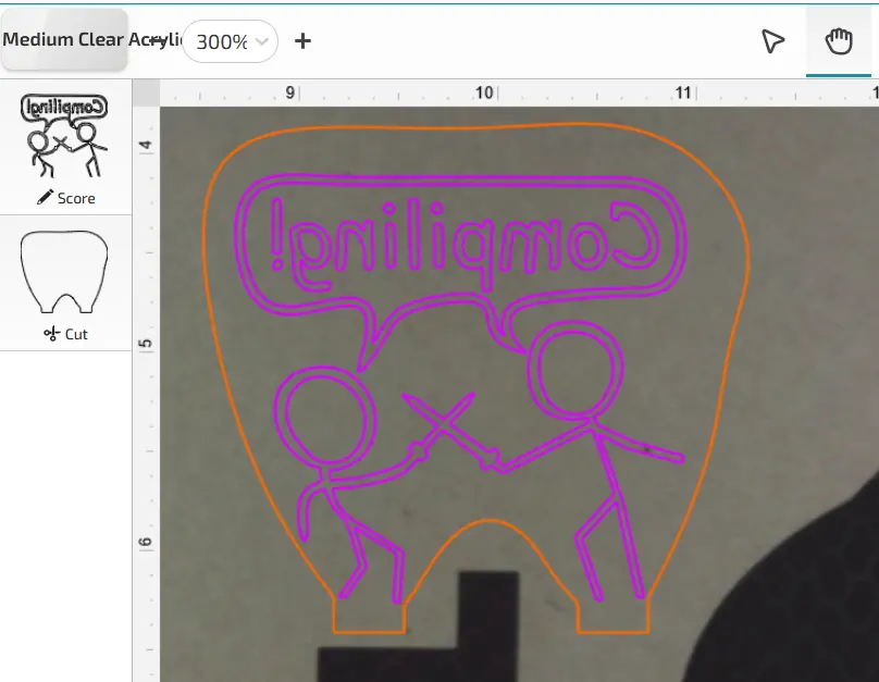
(Sixth image) Finally, sent the SVG to the Glowforge lasercutter and set the material to medium clear acrylic. The outer edge was cut, and the inner comic was scored.
Originally, I wanted to engrave the comic onto the acrylic, but the Glowforge interface did not recognize what I wanted to engrave exactly.
Scoring the design yielded superb results and was a viable alternative to engraving.
Construct and Test Prototype
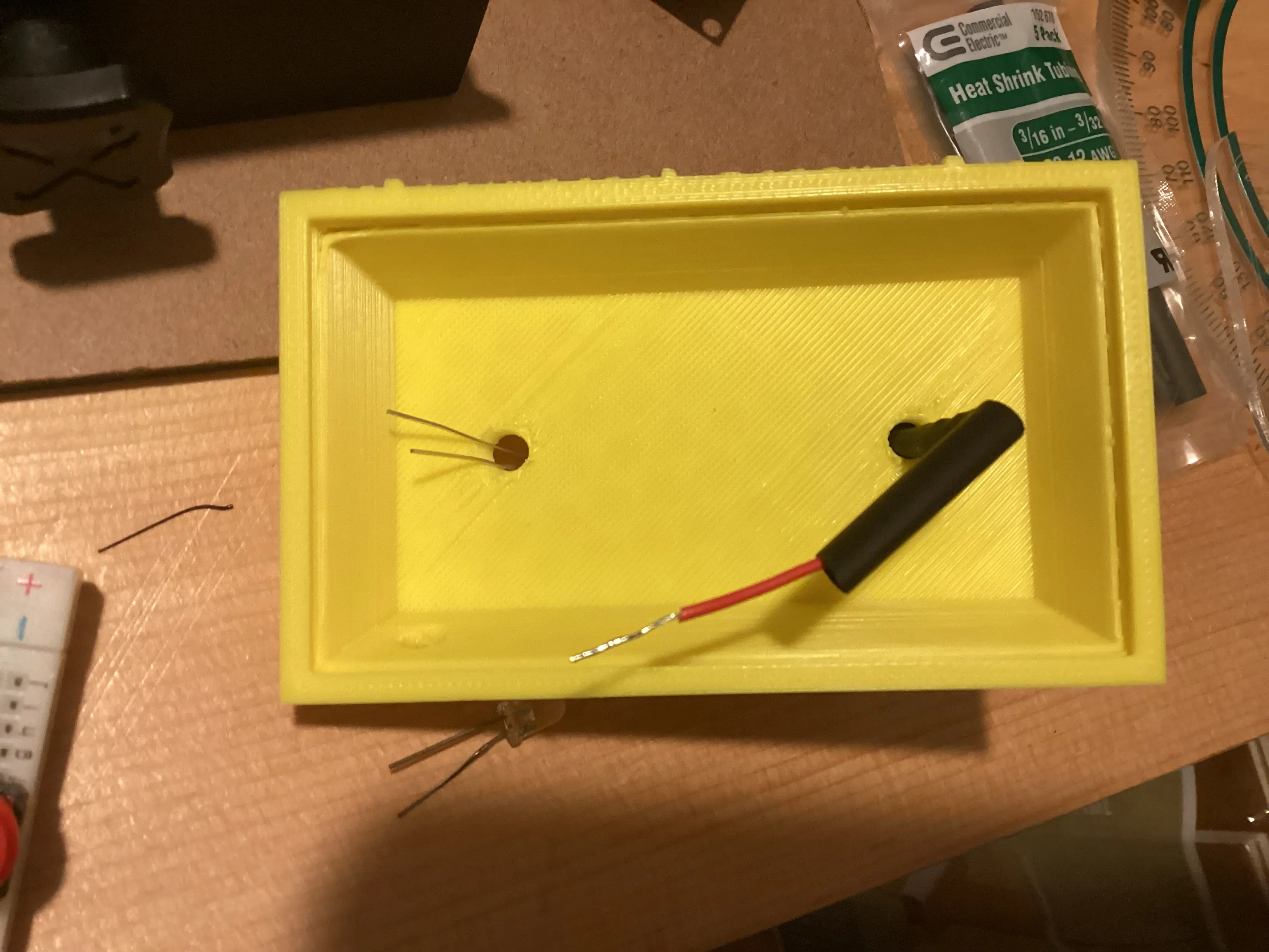
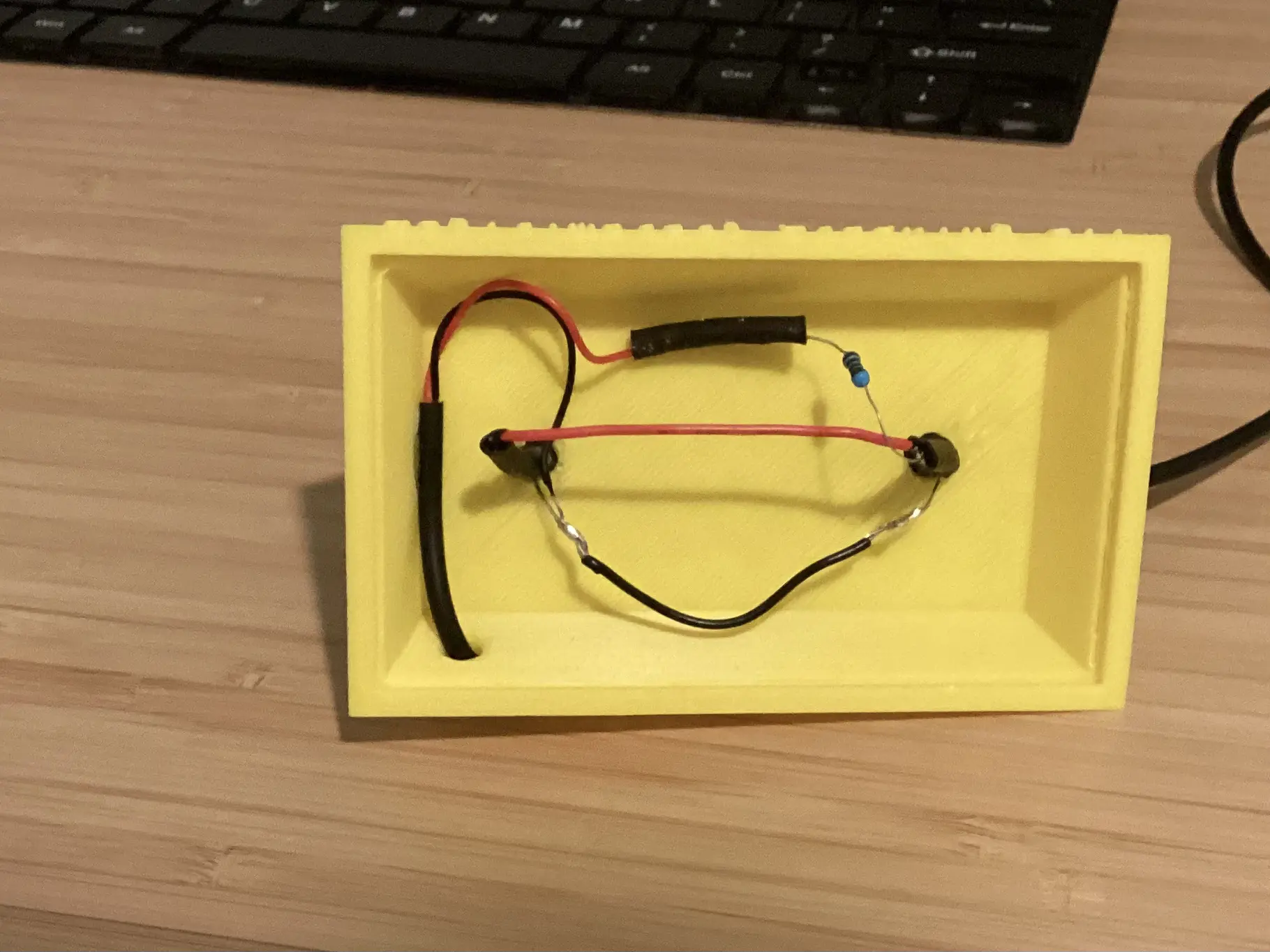
The night light was constructed using a 3D printer, lasercutter, LEDs, resistors, and an old USB cable. After lasercutting the insert and 3D printing the chairs with black PLA filament and the base with yellow PLA filament, I could put everything together. My 3D printer printed the slots for mounting the acrylic slightly too wide, so I had to pull the chairs slightly further apart while gluing them onto the base to provide tension which would keep the acrylic panel in place. Because of this, I did not have to redesign the base.
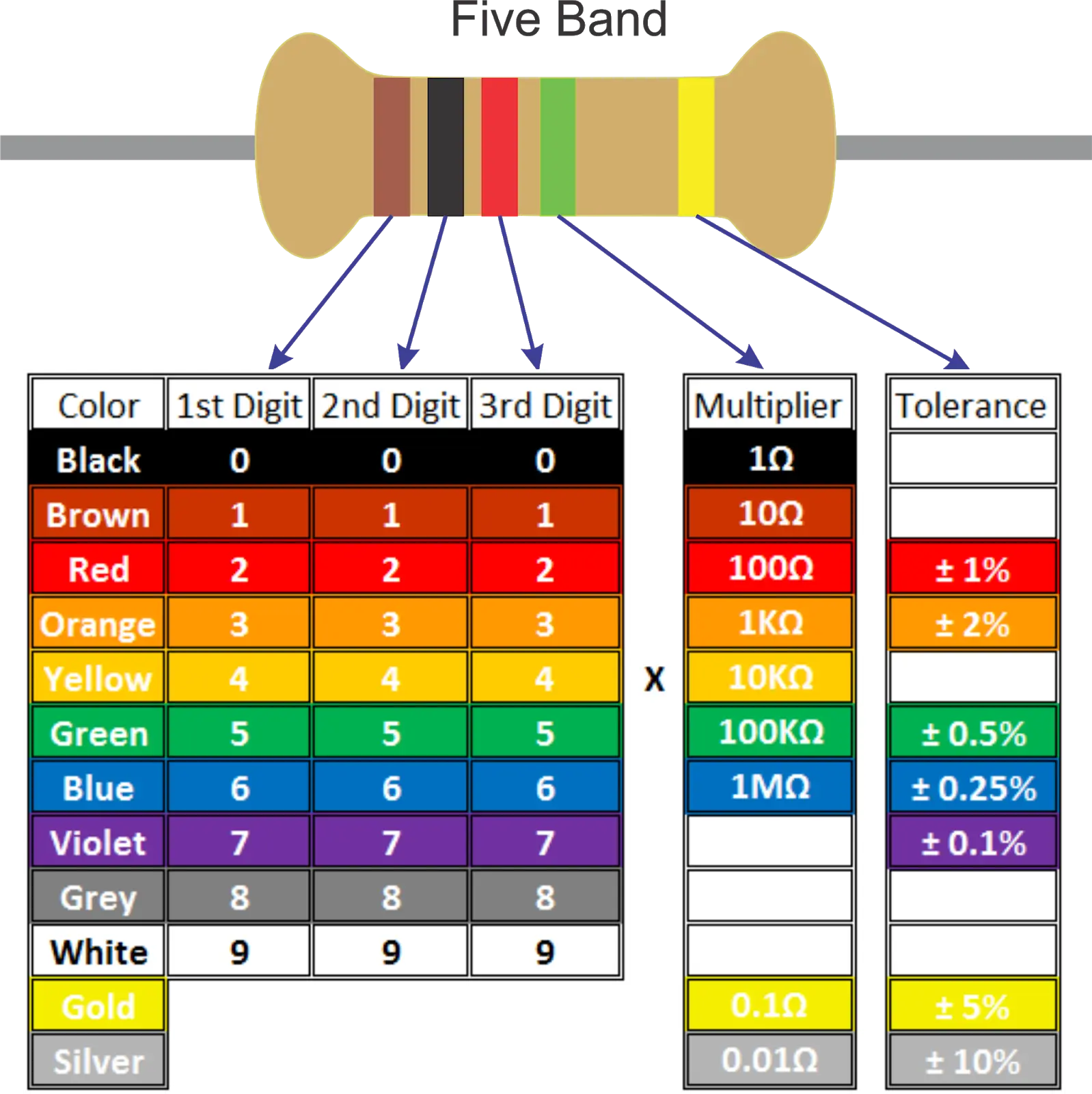
I did not have any 4-band resistors left, so I had to use a 5-band resistor.
Reading these is similar to how one would read a 4-band resistor, but the chart has slight differences.
The first three bands represent the digits of the resistance.
The fourth band is the multiplier, which is multiplied by the resistance determined by the first three digits.
The last band represents tolerance, and I used +/- 5%, so gold.
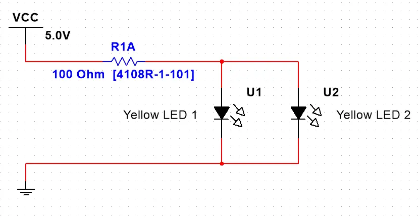
I determined that with a 5V 1A power supply and two yellow LEDs wired in parallel, I would need about 100 ohms of resistance with a tolerance of +/- 5% to ensure the LEDs would not burn-out.
This is represented by the bands "brown - black - black - black - gold."
Image credit: available here.
Evaluate Solution
During the process of making this night light, I had to solve multiple issues. Firstly, I needed to ensure a tolerance was added to measurements so that the LEDs would fit properly.
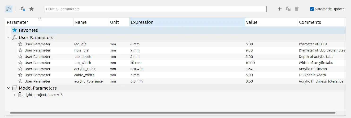
To do this, I used principles of parametric design in Autodesk Fusion 360 where measurements are defined as a variable.
When updated, the variable changes all measurements that depend on its value automatically.
I added acrylic tolerance (too much, oops!), a customizable LED diameter, acrylic tab dimensions for mounting, and a cable diameter for the USB cable.
Next time, I would decrease the acrylic tolerance to ensure a snug fit.
Additionally, I also had to remove double lines from the SVG file for the acrylic insert using Inkscape to lasercut the acrylic properly.
Now I know how to combine lines easily in Inkscape and would not try to engrave it in the Glowforge user interface.
Instead, I would move right to scoring the area as I experienced positive results using this method.
Reflection
Overall, this project was a superb way to review skills I had previously used. This project required CAD design, creating CAD drawings, along with accurate and precise measurement.
To produce the CAD design, I used my 3D printer for the base and the chairs, along with a Glowforge lasercutter at school to lasercut the clear acrylic insert.
I may use these methods and skills for my upcoming capstone project.
My wonderful teacher Mrs. Zienty at Worcester Technical High School taught me all these skills and more.
Documenting this project has also been a nice review of HTML, and I finally figured out how to implement 3D models outside of the homepage!