Design Process
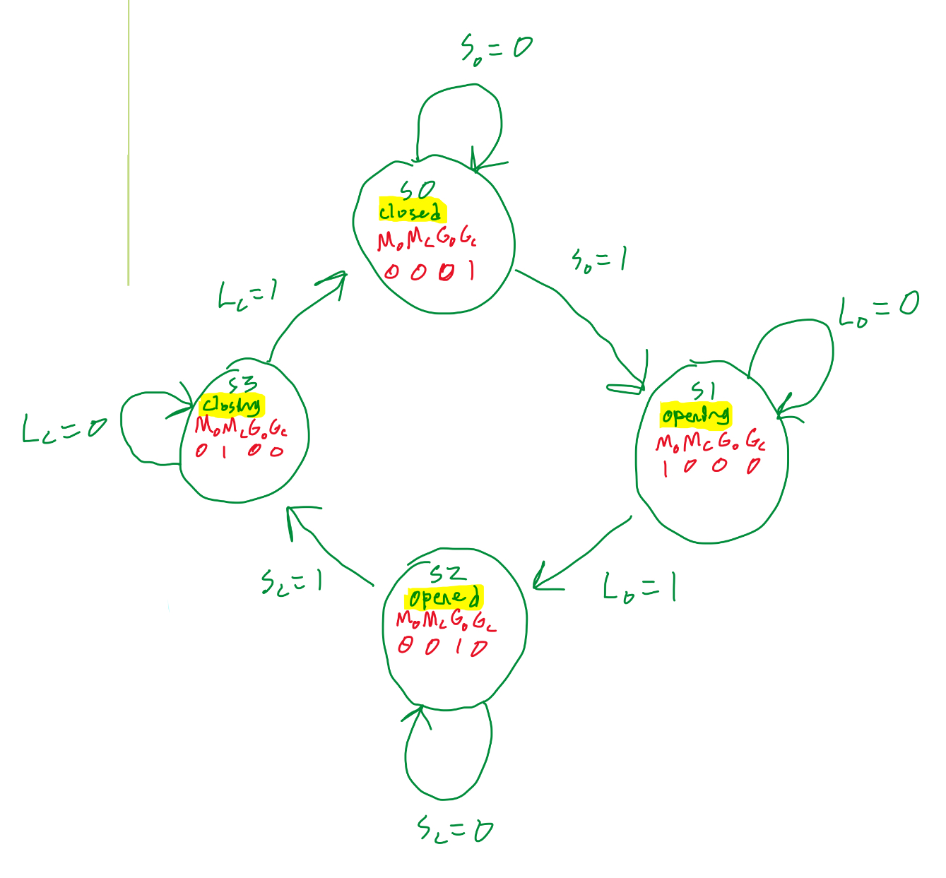
State Graph
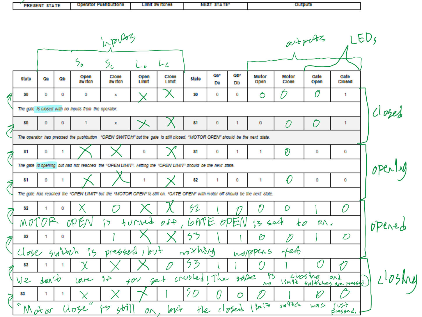
Transition Table
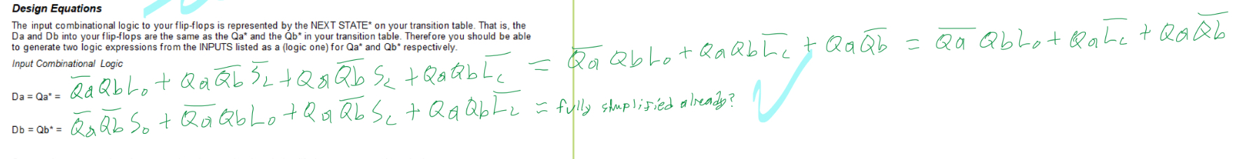
Boolean Algebra
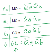
You might be thinking; What do all of these variables mean? Well, each state (S0, S1 ...) has input variables and output variables. When do we know to open the gate? When the Open Gate button is pressed. When the gate reaches the top, it needs to stop. To detect when the gate is fully opened, we used an "Open Limit" limit switch. The Close Gate button tells the circuit to close the gate. There is another limit switch, "Close Limit" that tells us that the gate is fully closed. Another question; How do we know which state, opening, open, closing, or closed we are in? We use state variables Qa and Qb, which are inputs to the flip-flops, in order for the circuit to know what to do next. Now that we have inputs, we also want the circuit to do something. The circuit also has multiple outputs such as the open LED, closed LED, motor close (tells the motor to close the gate) and motor open (tells the motor to open the gate).
The toll booth goes through multiple states. First, the gate is closed, meaning the closed limit switch is pressed down. Then the user presses the open button. This triggers the next stage where the gate begins to open and no limit switches are pressed. Once the gate reaches the top and is completely open, the open limit switch is pressed down. Circuit logic tells the motor to stop so it does not continue opening. When the user presses the close button, the gate begins closing and neither limit switch is pressed down. Once the gate is fully closed, the closed limit switch is pressed down and the process is once again at its starting point. This makes it an infinite circular state machine that will continue forever until stopped.
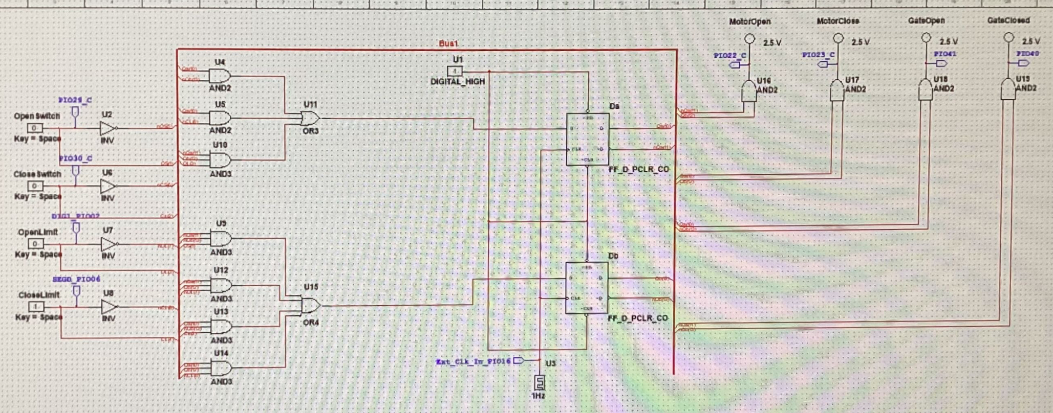
Circuit Schematic
VEX Breadboard Circuit
Conclusion
Our design process started theoretically. First we had to think of what states would occur in the operation of a toll booth. We thought of what the inputs and outputs were, similar to a black-box model, and then determined what states the toll booth would have. This process of determining how specific inputs resulted in specific outputs has been present in each of my Digital Electronics projects, and is an essential concept in the fields of electrical, computer, and software engineering. Once we had determined each state, we could assign state variables, Qa and Qb, input variables, and output variables. This went into a transition table which was later used to find the unsimplified boolean algebra for each of the output variables. This let us understand under which circumstances the motor should open or close the gate and whether the open or closed LED should be on. To make designing the circuit easier, we simplified the boolean algebra to use less logic gates in the schematic and on the microcontroller. Then I built the circuit while Lin made the state machine circuit in NI MultiSim. I found that reading the schematic was quite simple as it is a simplified perspective and description of the wiring. However, the SN754410 H-Bridge motor controller was difficult to orient as there was no clear indication or notch for which side contained pin 1. This caused issues while troubleshooting, along with my connection to the clock (CLK) pin on the microcontroller to pin 17 instead of the actual CLK pin which was 16. When I make another project similar to this, I would try to use better wire color coding and check pin numbers on circuit boards. Additionally, when I design custom PCBs, I will remember to label all input and output pins well as to reduce errors in connections.