Design Process
Project Overview
The goal of this project was to create a 60 second stopwatch. While the previous deli counter project used asynchronous flip-flops, this project required accurate timing. As a result, I needed to use synchronous flip-flops. In order to create this stopwatch, I used a synchronous MSI 74LS163 flip-flop for the ones place. D-Flip-Flops were used in a synchronous configuration for the tens place.
PLD Circuit
The circuit used in this stopwatch is very similar to that used in the deli counter project. As in the deli counter, two seven segment displays are multiplexed to display output on both. In addition, the ones place counts up from 0-9.
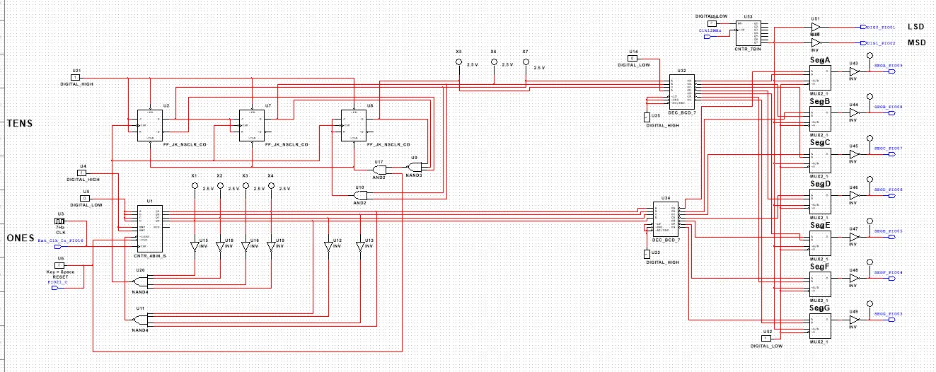
However, this project required accurate timing without the "ripple effect" which was present in the deli counter. To satisfy this requirement, I used synchronous counters such as the 72LS163 (shown as CNTR_4BIN_S in the PLD design) and three J/K flip-flops in a synchronous configuration. Also, the 74LS163 counter IC is "WYSIWYG" (What You See Is What You Get), meaning the last number defined by the end count is still visible. This differs from asynchronous counters and the 74LS193 counter as in that case the end count number that is detected only triggers the end signal and is not displayed, as it immediately updates and overwrites the end number. Because of this, a zero in the ones place had to trigger the tens place and the ones place had to "clear" at 9.
Conclusion
During this project, I learned how to create different synchronous counters using both MSI counters and SSI flip-flops. An asynchronous counter has each flip-flop triggered by the previous flip-flop. The propagation delay of the flip-flops causes a "ripple effect" in the output. On the other hand, a synchronous counter uses one clock to trigger all of the flip-flops simultaneously, eliminating the "ripple effect." Another difference between asynchronous and synchronous counters is that synchronous counters need extra AND gates connected to J and K to properly control the output of the counter. Asynchronous counters just connect J and K to VCC (toggle configuration).
The MSI counters 74LS163 and 74LS193 are both synchronous counters, but the 74LS163 has multiple disadvantages. Firstly, the 74LS163 can only count up, so it cannot be used in a down counter. Secondly, the 74LS163 requires additional logic to determine when to trigger the tens place, if used in a multi-digit counter system. The 74LS193 can count up or down, and resets immediately when the end count is triggered.
To design and create my circuit, I started with making the ones place. This process included adding a clock connected to the CNTR_4BIN_S and a reset switch connected to the "clear" pin of the MSI counter. A nine is detected on the MSI counter and goes to LOAD on the MSI counter. Also, a zero detected on the MSI counter triggers the SSI (tens place) counter by acting as the CLK input of the leftmost J/K flip-flop. The tens place counter consists of three J/K flip-flops wired in a synchronous configuration counting from 0-5. All of the CLK pins of these flip-flops are wired to the zero detection output from the ones place. The J/K flip-flops also must be wired to count upwards. In order to do this, all presets must be wired to digital HIGH, J and K of the first flip-flop must also be wired to HIGH, and J/K of the second flip-flop are connected to Q of the first flip-flop. As with any synchronous J/K flip-flop counter, J/K of the third flip-flop are connected to the Q pins of the first and second flip-flops through an and gate. Also in the tens place, a six is detected for the end count through the application of a three-input NAND gate. The NAND gate is wired to all CLR (clear) pins of the J/K flip-flops. This allows the circuit to automatically reset at 60. The reset switch is also connected through an AND gate to the end detection of the J/K flip-flops to allow the circuit to be reset at any time using the aforementioned reset switch. Then both displays are connected to the multiplexer logic so that both seven segment displays can be used. Physical circuitry remained the same in this project as the deli counter. This included wiring Pin 16 of the Digilent PLTW S7 to one of the CLK values, and Pins 9-3 (wires 9-3 in descending order) to segments A-G respectively. To add the reset switch, Pin 20 was connected to Switch 1.
Lin and I made very similar circuits to create a 60 second stopwatch. The only main difference is that Lin used a simple inverter and wire to detect a zero and trigger the tens place. On the other hand, I used two inverters and a NAND gate to detect a zero.