Design Process
Project Overview
In this project, I created a vote tracker that gave the final voting result
based on the inputs of members of a board of directors.
The members included a president, vice-president, secretary, and treasurer.
It is supposed to be a secure way to vote without any discrepancies as
to the legitimacy of the result.
Only 2-input AND gates (74LS08), OR gates (74LS32),
and NOT/inverter gates (74LS04) are available.
In the case of a tie, the President's vote counts.
Additionally, there is no "opt out" of voting.
Truth Table with Boolean Algebra
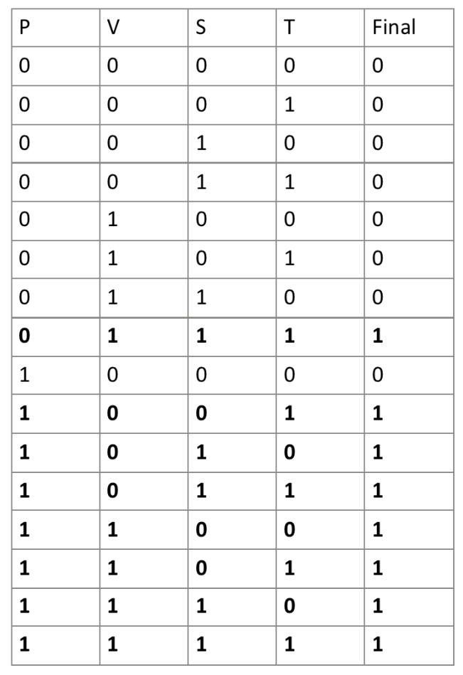
This truth table lists all possible outcomes from the voting.
It allows us to see patterns in the output that could eventually be simplified using boolean algebra.
In a truth table, there are 2^n rows, where n is the number of input variables.
For example, here there are 4 input variables (P, V, S, and T), so there are 2^4 = 16 rows.
Additionally, in the case of a tie, the President's vote is the deciding factor.
This is seen in the truth table when it is:
* 1001: P AND NOT V AND NOT S AND T
* 1010: P AND NOT V AND S AND NOT T
* 1100: P AND V AND NOT S AND NOT T.
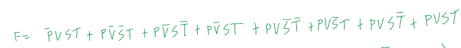
Above is the unsimplified logic expression for the voting outcomes. It is in Sum of Products (SOP) form because I took each minterm (part that gives a TRUE result) from the truth table and added it in this SOP expression.
Unsimplified Circuit
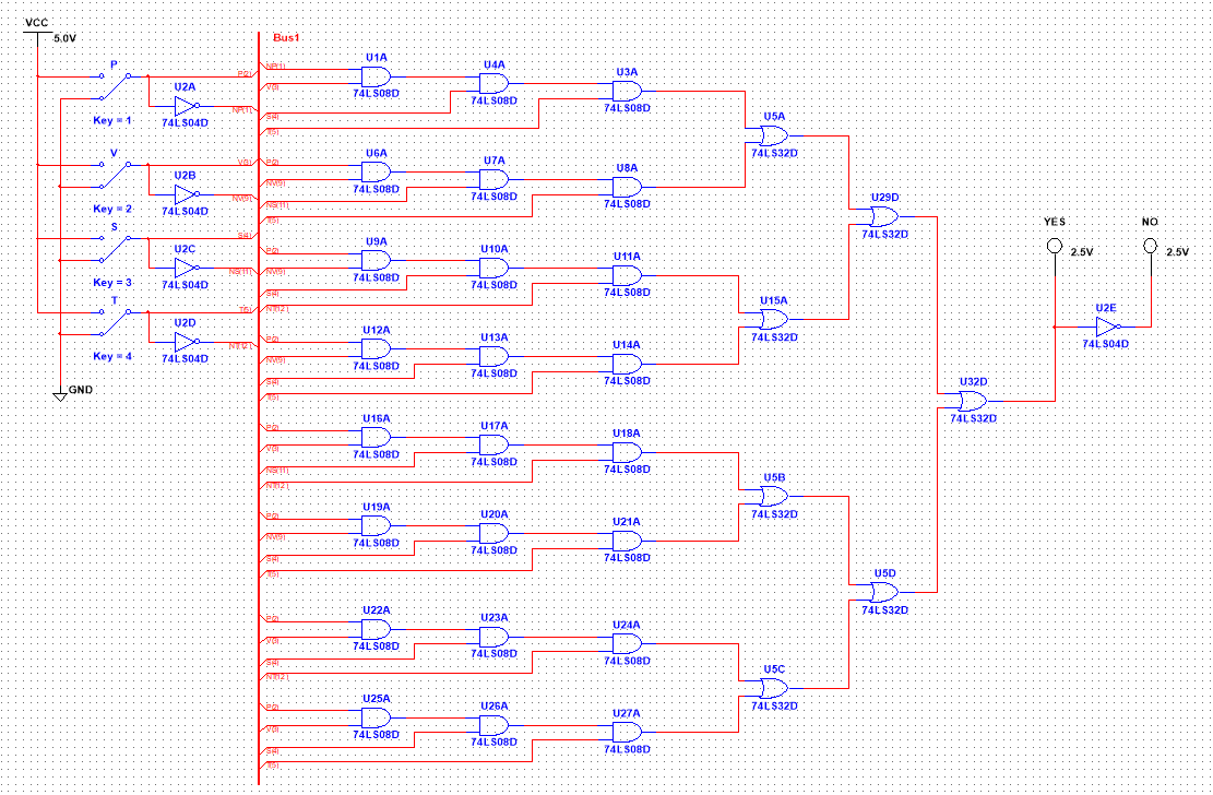
This is the unsimplified circuit derived from the logic expression above. I used five 74LS04 inverters/NOT gates, a hefty 24 74LS08 AND gates, and seven 74LS32 OR gates! This means that one 74LS04 inverter/NOT IC (Integrated Circuit/Chip) would be used, six 74LS08 AND ICs would be used, and two 74LS32 OR ICs, for a total of nine ICs. This would be very tedious to build in real life, and quite difficult to troubleshoot. I even used a bus in the design to simplify the circuit in National Instruments Multisim CAD!
Boolean Algebra Simplification
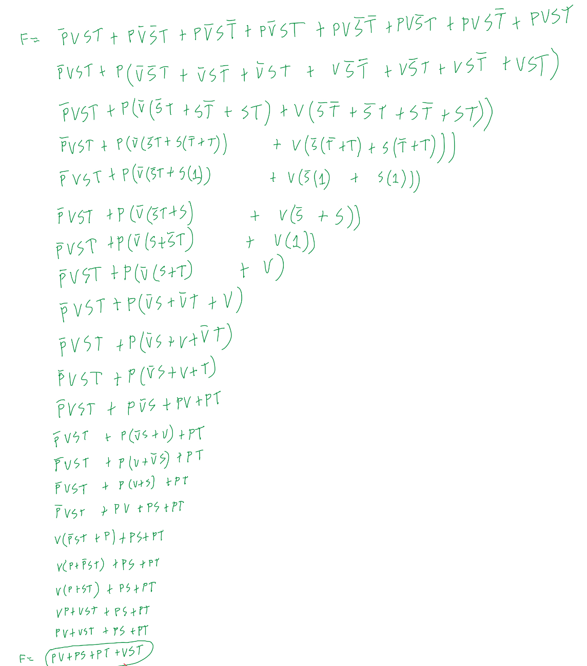
This is the simplified boolean algebra expression, which is much neater than the unsimplified expression.

Simplified Circuit
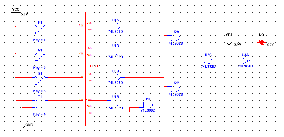
This is the simplified circuit.
It only requires five 74LS08 AND gates, three 74LS32 OR gates,
and one inverter (which is just to add another LED, optional).
This brings it to a total of 9 gates, which is only four ICs,
less than half of the nine ICs in the unsimplified circuit.
I still decided to use a bus to simplify troubleshooting and the overall layout.
The simplified circuit is far superior, because it has less latency,
is easier to build and troubleshoot, and requires less components (thus decreasing cost).
Bill of Materials
This is the list of all the components used in the simplified circuit on a breadboard.
| Component | Quantity |
| 74LS08 2-input AND Gate | 2 |
| 74LS32 2-input OR Gate | 1 |
| 74LS04 NOT/inverter Gate | 1, OPTIONAL |
| Red LED | 1, OPTIONAL |
| Green LED | 1 |
| 330 Ohm Resistor | 2, 1 is optional for red LED |
| Wires | About 30 |
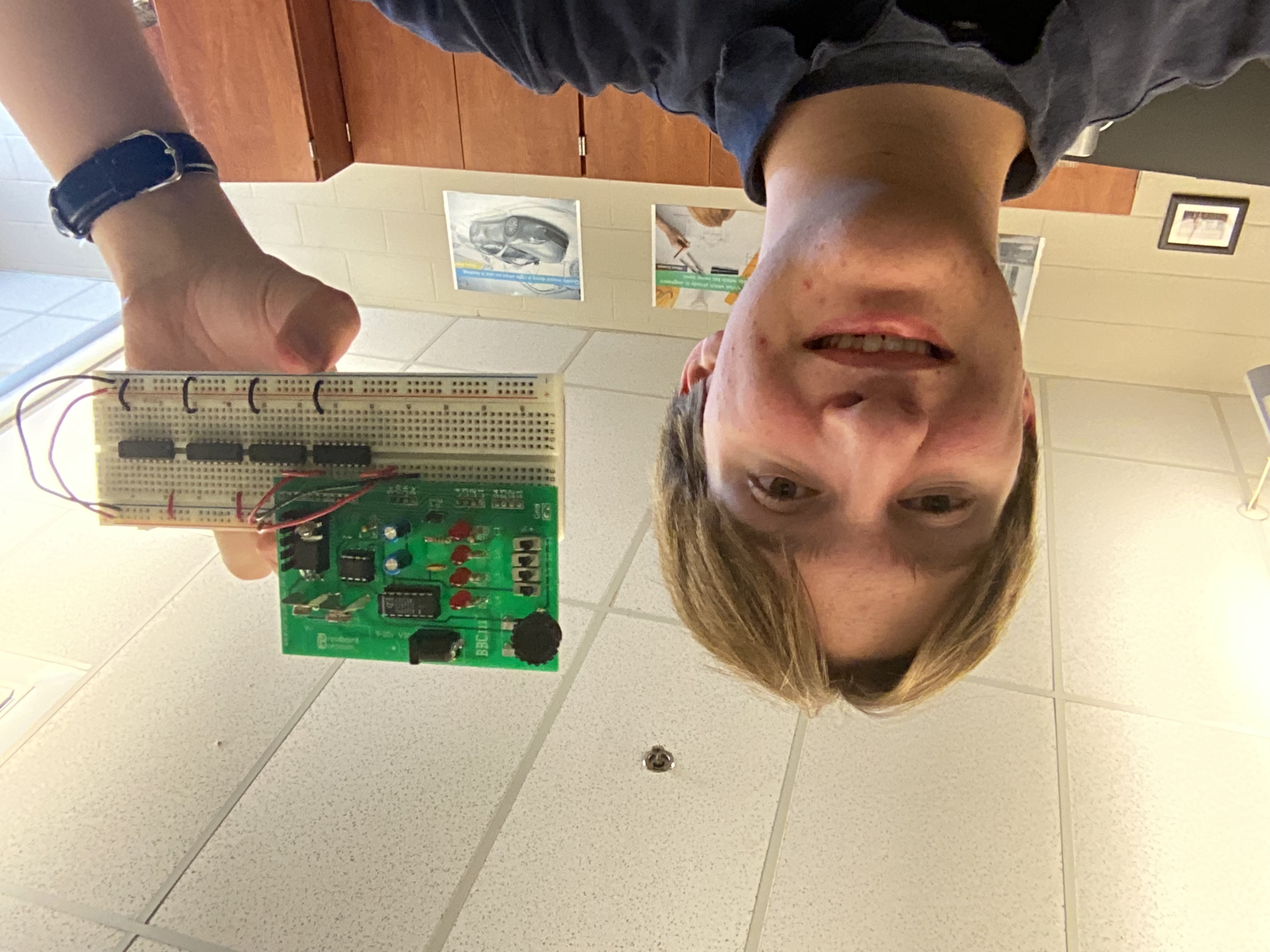
Breadboarding
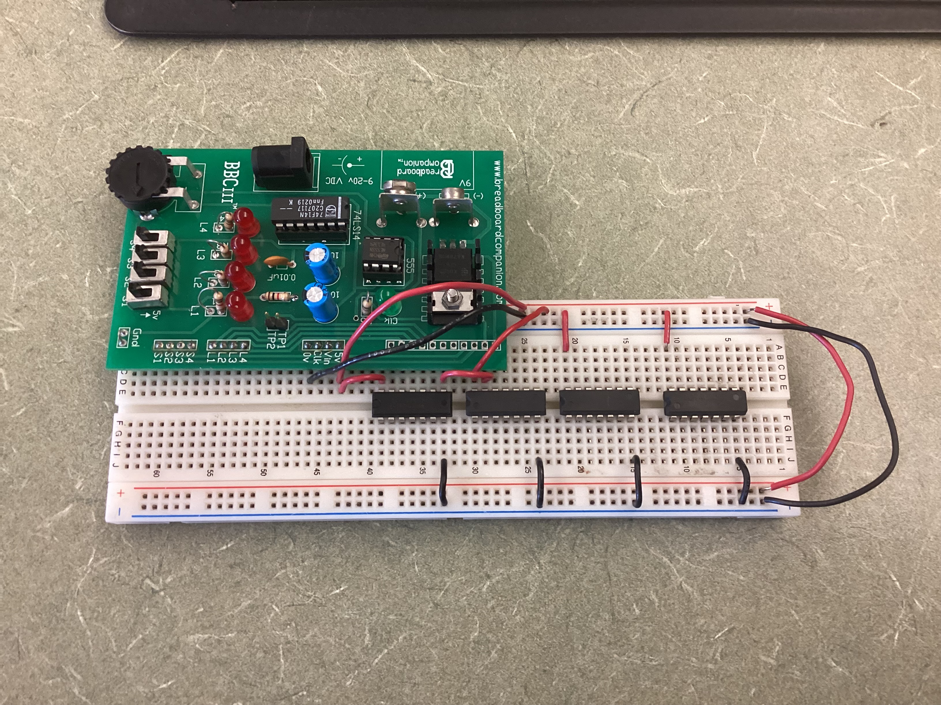
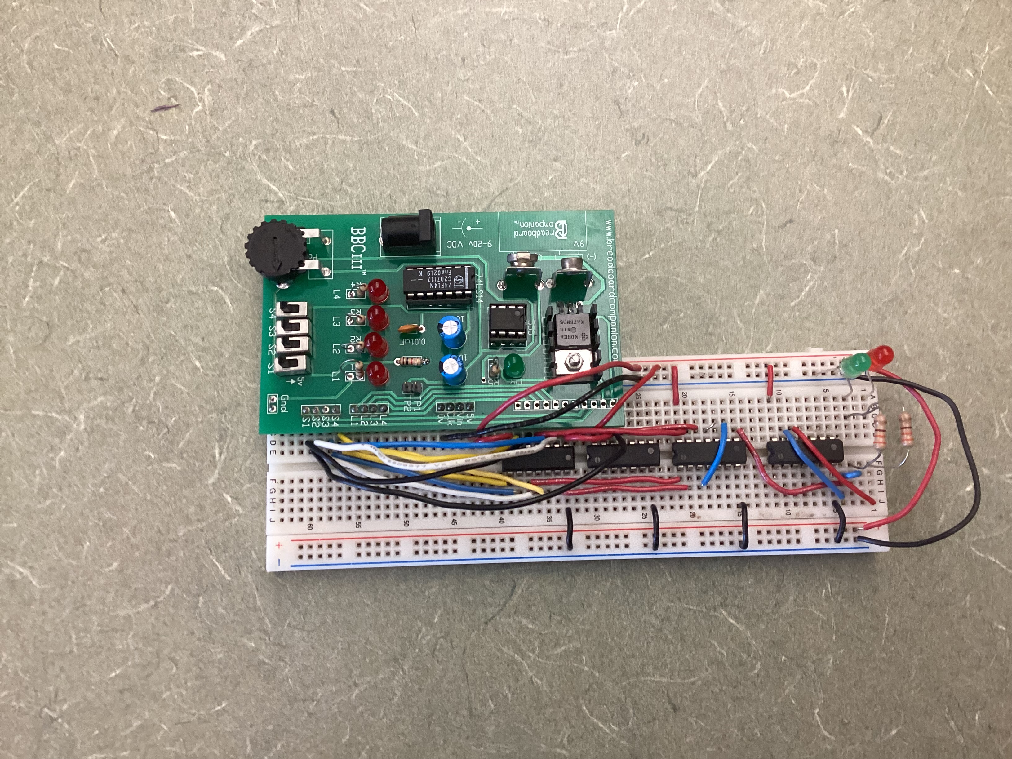
In the first image, power (VCC) and ground (GND) are bridged to provide access on both sides of the breadboard. All ICs are properly powered and grounded.
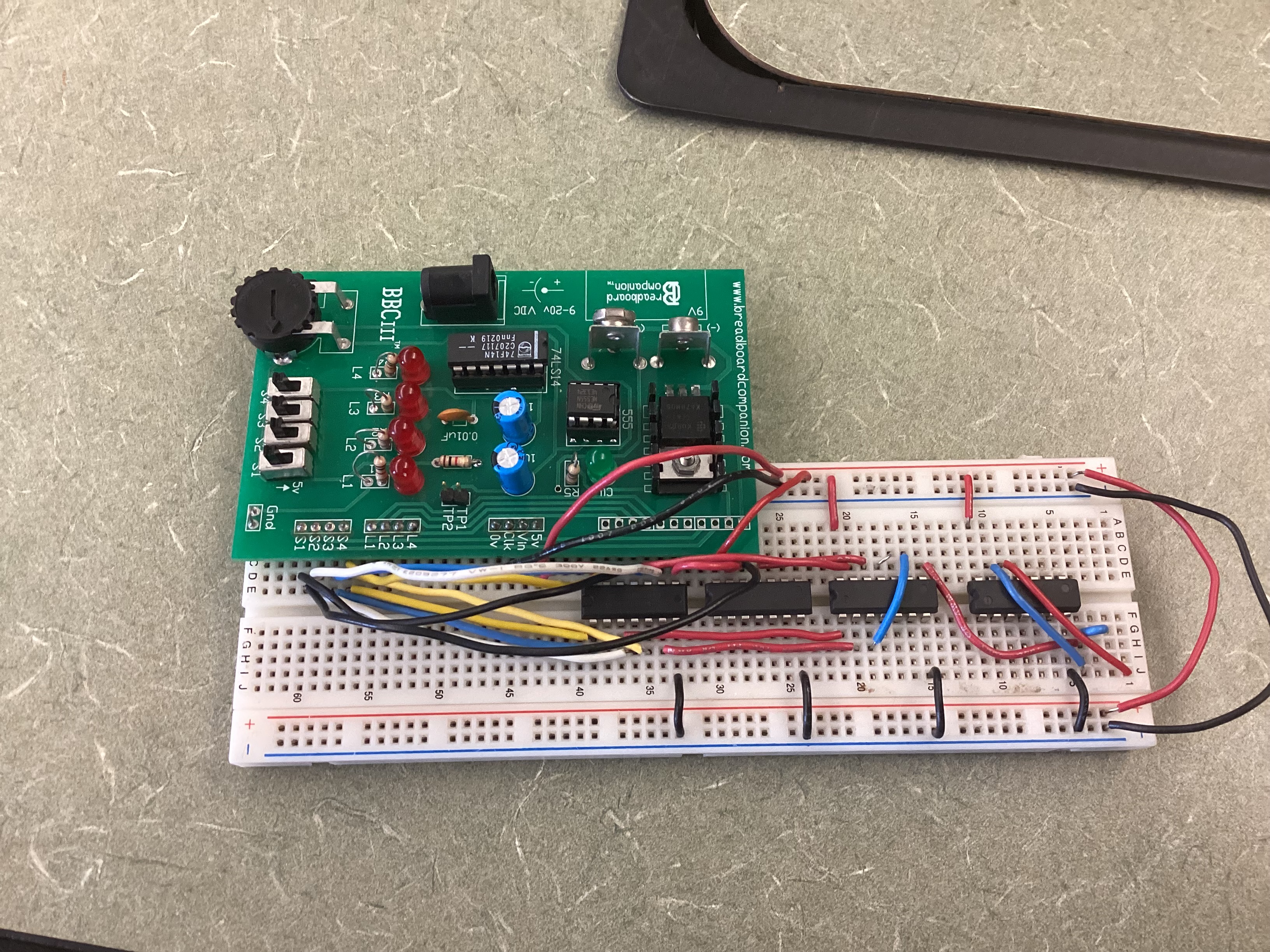
The second image shows the complete logic connections that transmit the data from each IC to the next so it is evaluated correctly.
Finally, the LEDs (Light Emitting Diodes) are added in the third image to provide a usable, intuitive output of the votes.
330 ohm resistors were used in front of the LEDs as they can handle 3.3V, but the voltage the ICs use is 5V. This ensures that the LEDs do not burn out. I made a few mistakes, like using the wrong ICs (It is really hard to see the tiny numbers printed on top). I fixed this by swapping out the ICs. Also, the President wire was off by one row in the breadboard, but that was easy to fix.
Conclusion
This project taught me how to analyze a situation using inputs and find the output based on rules. I learned how to apply boolean algebra to immensely simplify a Sum of Products equation in order to use less components. In this project, I realized the vast opportunities for improvement in troubleshooting, efficiency, and cost-effectiveness just by simplifying the circuit. This is the reason why Boolean algebra is used in the industry, to reduce costs and space taken by ICs. In the newest electronics, space is a valuable commodity that is very limited by the design constraints, thus demonstrating the need for a simplified circuit to be used. To wrap it up, I went from a simple problem to a truth table showing outputs. After this, I simplified the SOP expression using Boolean algebra to reduce the amount of ICs needed in the circuit. Then I modeled the simplified expression to make a circuit using NI Multisim, and finally I created a physical circuit using a breadboard. And it is always important to remember, that without documentation, a project is no longer a project.