Design Process
Project Overview
Many stores and delis have customer counters to organize and keep track of customer orders. You take a small ticket with a printed number, afterwhich your number is called once your order is ready. This project involves creating a number counter using two seven segment displays and flip-flops. The counter counts up from 0, and pauses at 80. Once a reset switch is toggled, which can occur at any time, the counter resets to 0.
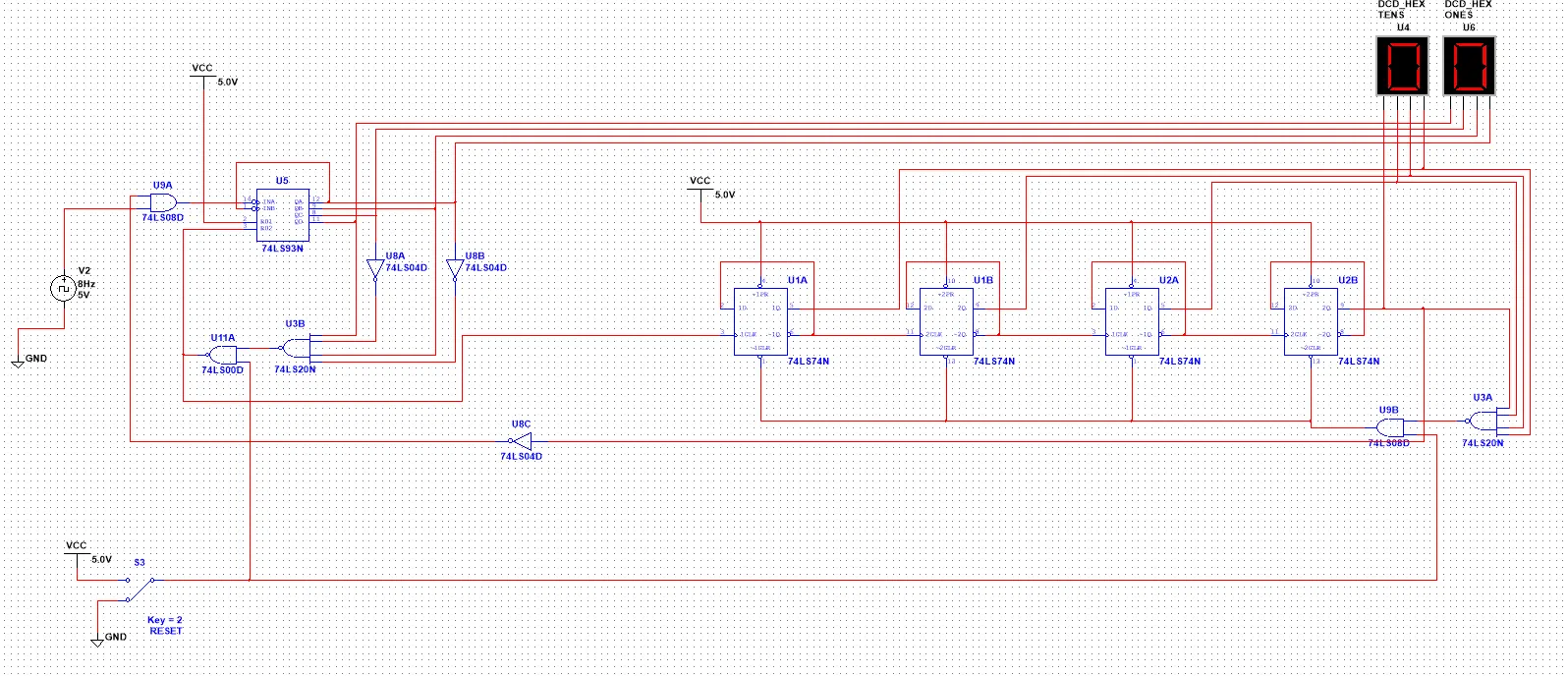
NI MultiSim Circuit
PLD Circuit
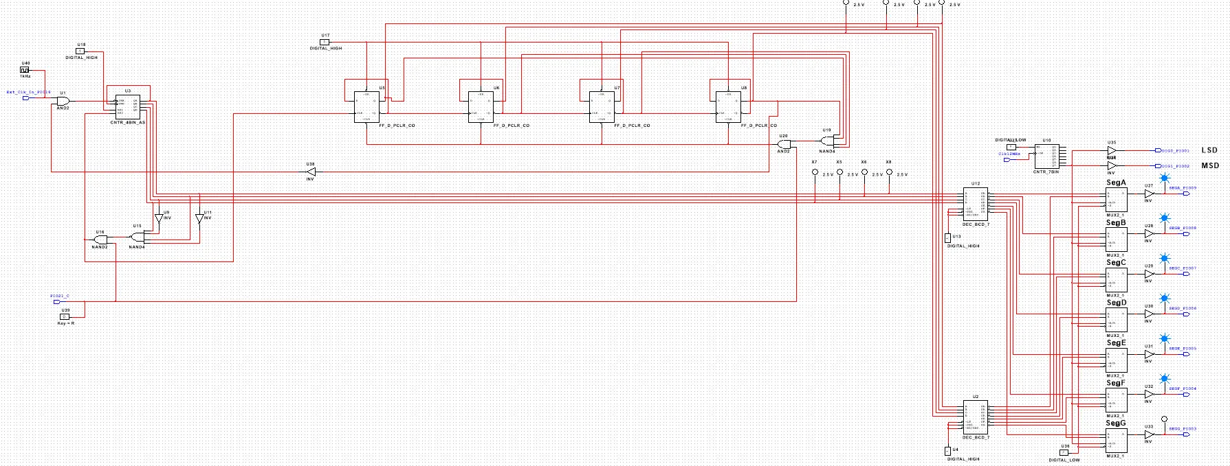
The PLD design mode is similar to the regular design mode in NI MultiSim. The main difference is that it is geared towards programming microcontrollers. Instead of actual electrical components such as ICs, virtual components are used. An example of this is that in the regular design mode, an AND gate is a 74LS08 IC. However, in PLD mode it is simply AND2 (meaning 2 input AND gate). Another feature of the PLD design mode is input and output pins. These correspond to physical pins on the microcontroller. Input connectors and output connectors take either inputs (such as switch inputs) or outputs (such as an output to an LED). Once the logic and circuit are complete, the entire design can be transferred to a microcontroller (in this case the Digilent PLTW S7). The microcontroller will then execute the "code" defined by the circuit schematic. This is effectively programming with circuit logic.
Breadboard Circuit
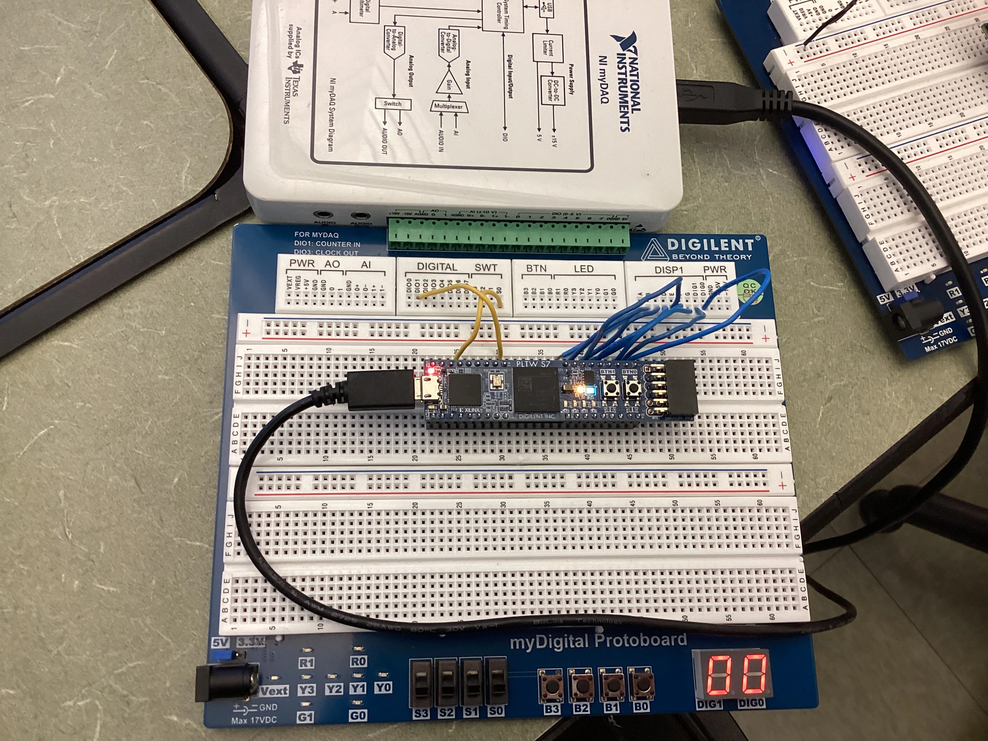
Bill of Materials
This is the list of all the components used in the simplified circuit on a breadboard.
| Component | Quantity |
| Digilent PLTW S7 Microcontroller | 1 |
| myDigital Protoboard (Breadboard with SSD) | 1 |
| Wires | 11 |
Conclusion
The circuit uses a clock input (CLK) to control the number increments. A CLK signal goes to an AND gate. If the reset switch is also HIGH, then the signal proceeds into the MSB chip. This outputs an incrementing number that represents the ones place and resets when 10, or A is detected. When it is reset, a CLK signal is sent to the flip-flops for the tens place. These 4 flip-flops are in toggle mode since D is connected to NOT Q. At the end of this flip-flop assembly, a single wire is connected to Q of the MSB flip-flop. This receives a HIGH value when the MSB is 1, meaning the display shows an 8. The output of this wire is sent through an inverter (so it becomes a 0) to the AND gate in the beginning to cause the counter to suspend. When the user toggles the reset switch, a signal is sent to the ones place counter and to the tens place counter to activate the CLEAR pin of every flip-flop. This automatically resets the value of every flip-flop to a 0.
In this project, I used both SSI (Small Scale Integration) and MSI (Medium Scale Integration) components. SSI is used in smaller projects that are not mass-produced. These types of circuits require basic components to be wired manually.
On the other hand, MSI circuits contain everything needed in a small form factor, which is advantageous in mass production. The basic flip-flops represented an SSI circuit, while the one's part of the circuit used an MSI component. The MSI component contained all flip-flops and connections needed to create a counter, which is very practical.
However, the MSI circuit also has a few drawbacks. The MSI IC 74LS93 includes 4 flip-flops, which can be overkill for an application that only needs three. In addition, propagation delay may be increased. This circuit is also asynchronous, meaning there is a "ripple effect." The "ripple effect" is a glitch or ripple in the output display of an asynchronous flip-flop counter system. Each flip-flop has a propagation delay which is the time needed for the flip-flop to function. As each flip-flop is connected in series, onto the previous flip-flop, there is a slight time difference in each output. This causes the ripple sometimes seen in digital displays or clocks.
There are multiple ways to make this circuit slightly differently. To suspend or reset the count, AOI logic can be performed. I used a one wire approach that used only one wire and an AND gate to suspend the count at 80 based on when the MSB became a 1.