Design Process
Project Overview
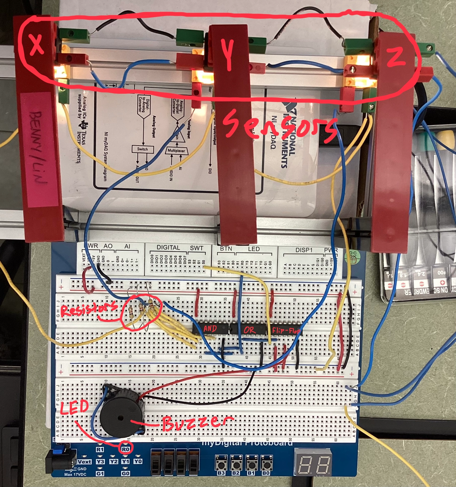
Everyone has printer problems. It is very important to know what the issue is in order to fix it. This project involved building a copier jam sensor module that uses boolean logic to detect when there is a jam. When a jam occurs, an LED is lit. Additionally, D-flip-flop is used to keep a buzzer on until a reset switch is toggled. This helps to alert users later if they are not present when the jam occurs. It also tells everyone that someone jammed the copier.
Photoresistors needed to be used to detect the jam. Also, the circuit requires resistors to continuously provide power to the circuit, even when the photoresistors do not provide input power.
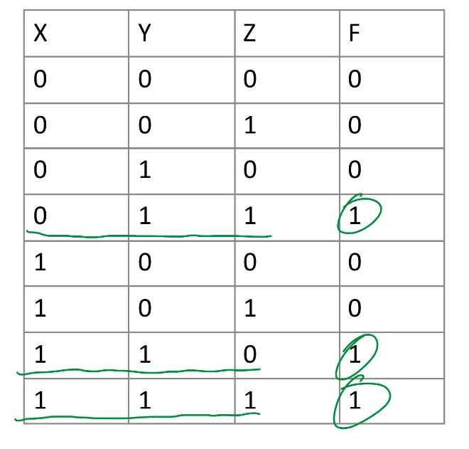
Truth Table
Boolean Algebra

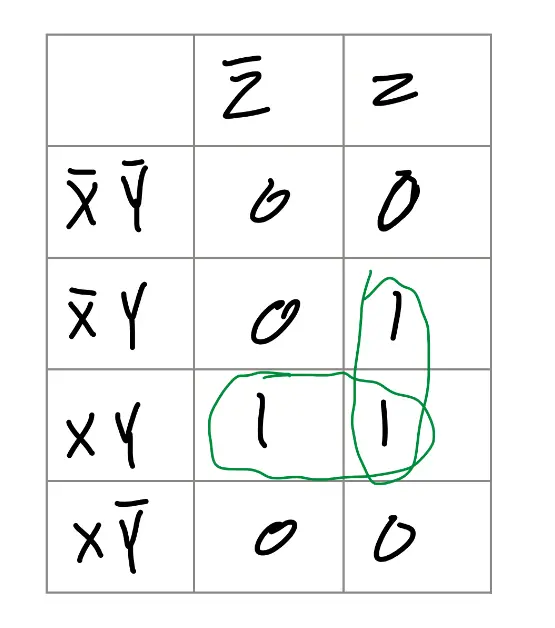
K-Map
Simplified Expression
From using boolean algebra along with K-Mapping, the Product of Sums (POS) minterms have been simplified to the following expression:
F = YZ + XY
Copier Construction

Wiring Diagrams
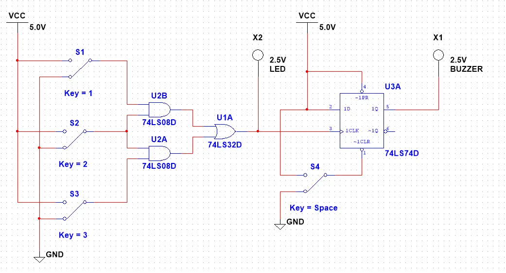
Reading the external wiring diagram of the flip-flop was pretty simple. I looked at the inputs and outputs of the flip-flop and traced these back to their respective pins on the pinout diagram. My circuit schematic definitely helped in this process. Including the flip-flop was not too hard as the flip-flop only needed the output of the boolean logic as a clock (CLK) input, along with the Q out being the buzzer. Power was supplied to PRESET and D in (Data input). To stop the buzzer, a simple dip switch was implemented to either power or ground the CLEAR pin of the flip-flop.
Component Implementations
Resistors were implemented in order to make the photo-transistors function. In the circuit, when the photoresistors receive light, they output a logic high. Otherwise, since electricity chooses the easiest path, a small magnitude of power is drawn through a 5.2K ohm resistor on a 5V power supply. This will make it "choose" which source to obtain power from to provide the input. The AOI combinational logic detects when two adjacent photoresistors return a logic LOW (meaning 2 pieces of paper are next to each other). The signal lights an LED directly whenever there is a jam. A flip-flop is also triggered whenever there is a jam, causing a buzzer alarm to sound. The difference between the LED and the buzzer is that the LED turns off when the jam is resolved, but the buzzer stays on until the clear (CLR) switch is toggled. But if you leave the clear switch on, then the buzzer will never sound as the clear switch overrides any input to the flip-flop.
Bill of Materials
This is the list of all the components used in the simplified circuit on a breadboard.
| Component | Quantity |
| 74LS08 2-input AND Gate | 1 |
| 74LS32 2-input OR Gate | 1 |
| 74LS74 D-Flip-Flop | 1 |
| 5.2K Ohm Resistor | 3 |
| Buzzer | 1 |
| Wires | About 25 |
Conclusion
This project used a flip-flop to hold the signal of the jam to keep the buzzer on continuously. It used a combination of sensors, boolean logic, and output devices such as a buzzer to alert a user of a copier jam. This circuit could be very helpful in copiers to identify the source of the jam. I learned how to use clocks and flip-flops, how flip-flops work, along with how to wire photoresistors. This circuit is ethical as it is intended to solve copier jam issues.