About the Project
Introduction
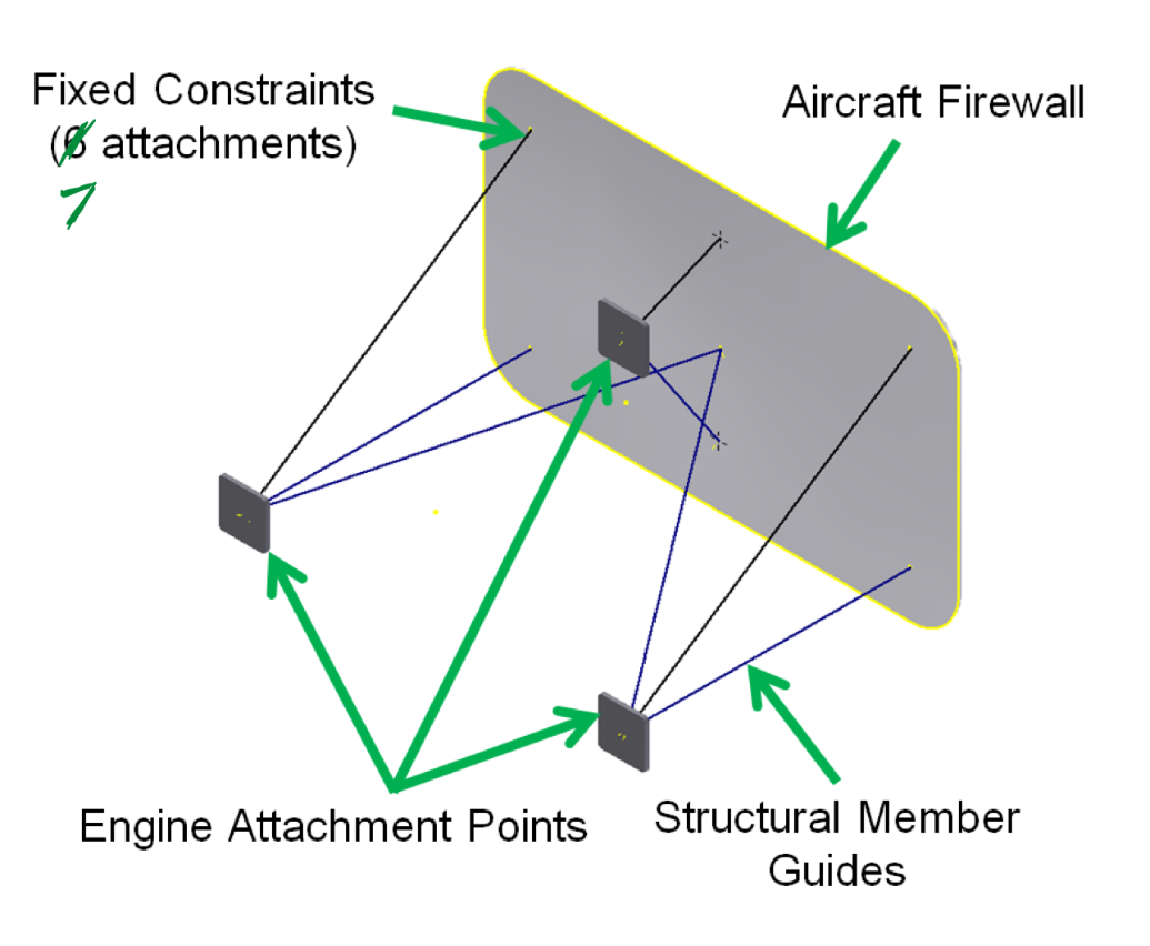
In this project, I designed a motor mount structure for a Lycoming O-300 engine. The motor weights 250 lbs, and the weight is distributed over three attachment points. During the flight, the aircraft can experience between -3 and 6 G, meaning that the mount must withstand these conditions. In addition to this, all structural members must be 1 1/2 in ANSI pipe, and miters must be applied to the frame members for construction. A 3D CAD model is needed to ensure all parts are assembled properly and can be tested to verify the characteristics of the engine mount.
Designing the Frame
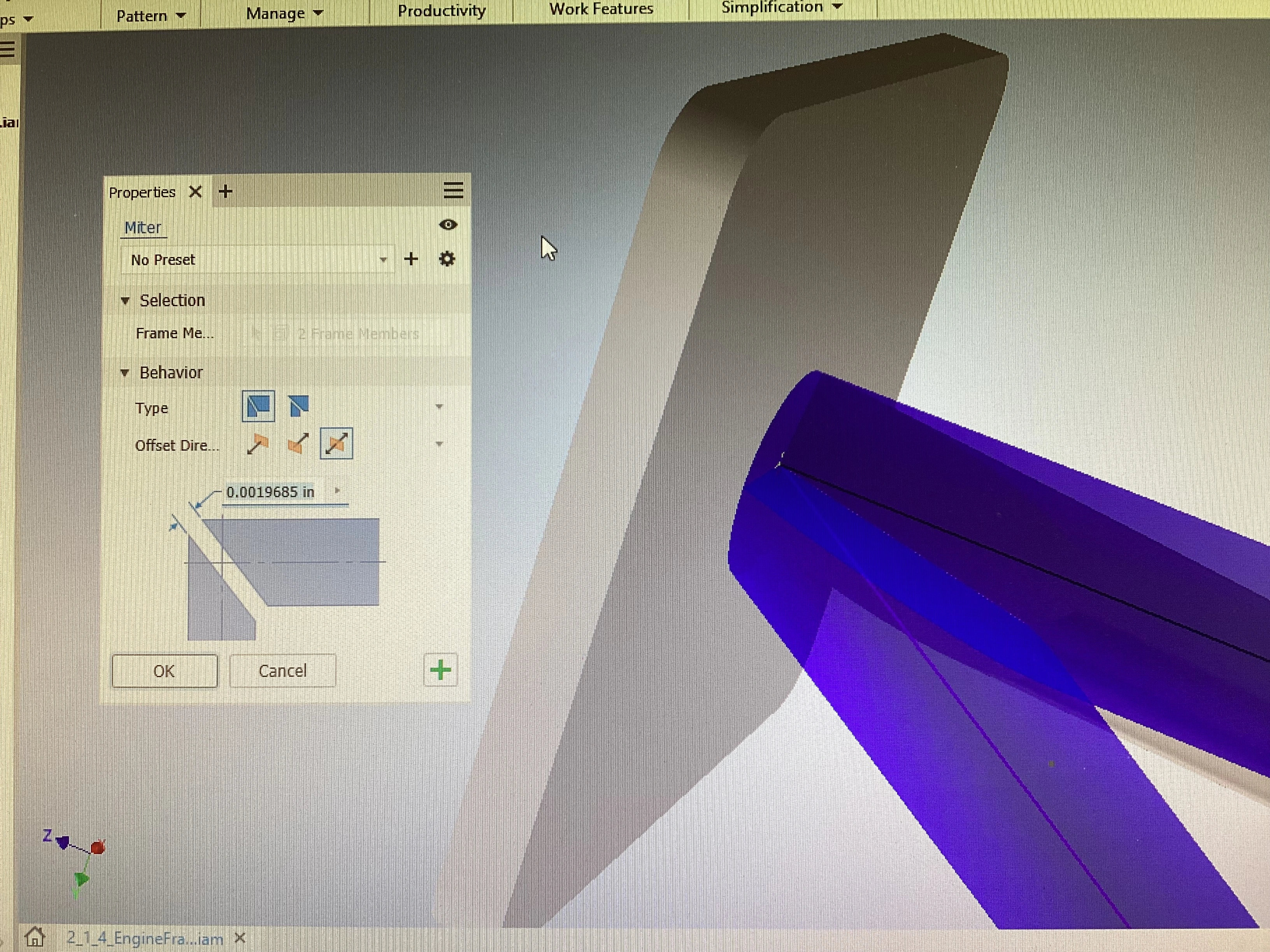
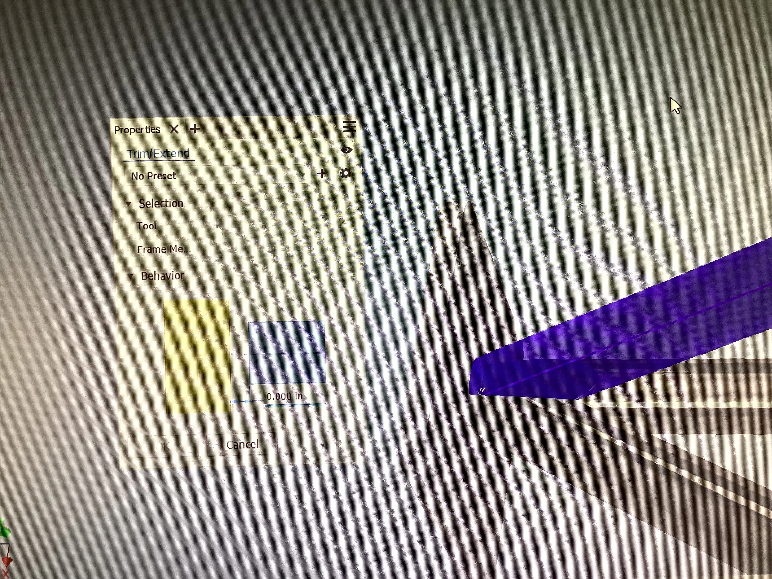
In order to build the frame, I mitered and trimmed the pipe parts. Applying a miter to pipes allows them to be welded together at an angle, as seen in the image. Trimming pipes ensures that there will be a flat surface for the engine attachment points to attach to. In Autodesk Inventor, I started with a basic 3D sketch of the frame. Next, I used the built-in Frame Generator to place the ANSI pipe along the lines of the sketch. After that, I applied a miter to any groups of pipes colliding, and trimmed the ends to line-up with any flat surfaces (such as the firewall and engine attachment points).
Material Choice
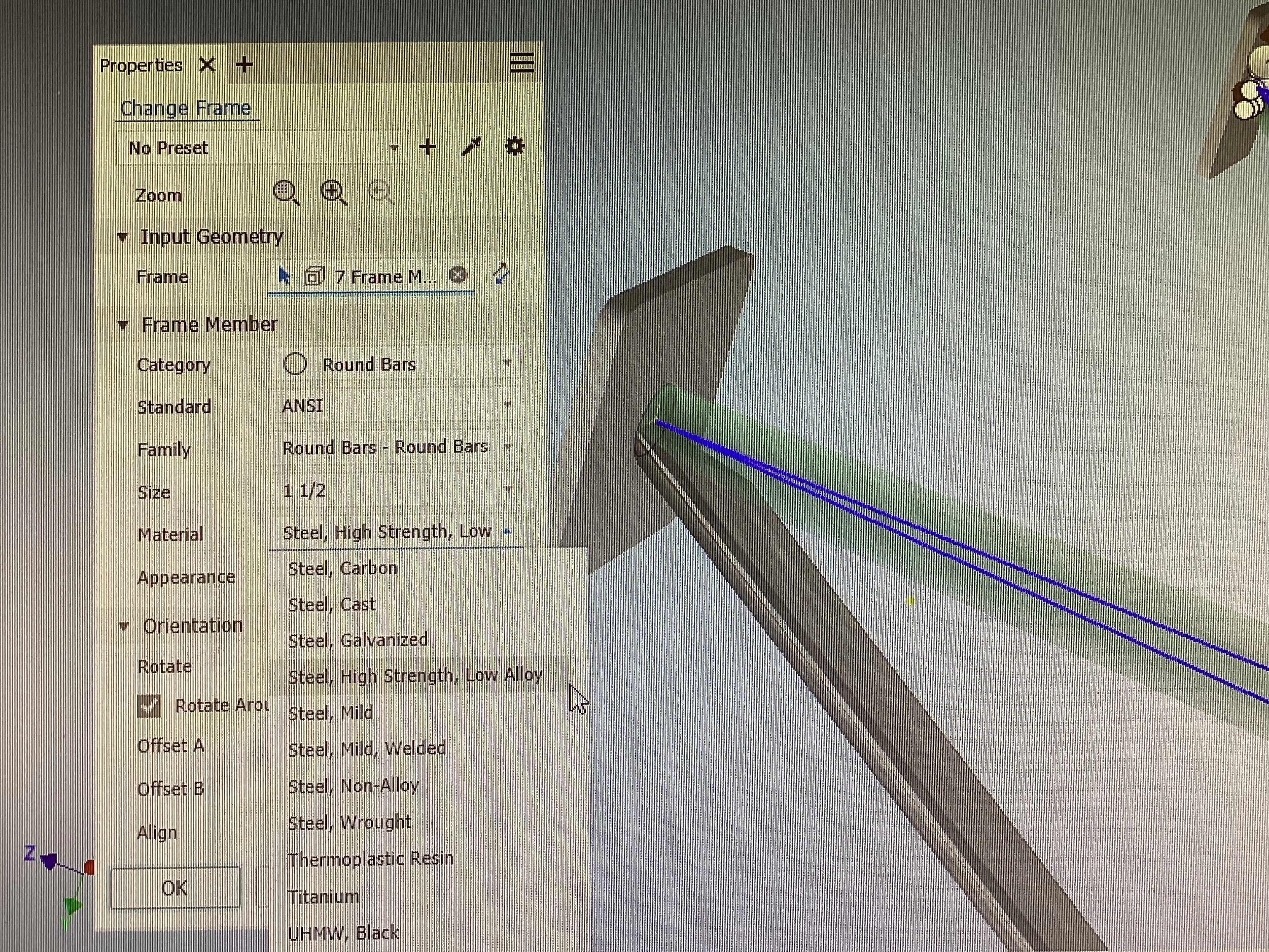
The engine mount must have a very high modulus of elasticity (meaning it is very stiff), and must have high temperature resistance due to the environment. To meet these criteria, I used high strength, low alloy steel for the ANSI 1 1/2 in pipes.
Adding Forces for Simulation
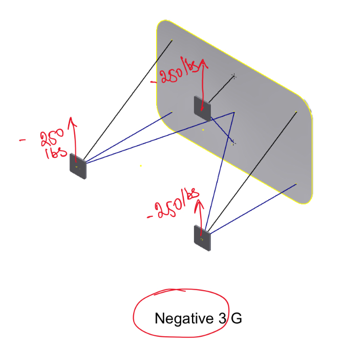
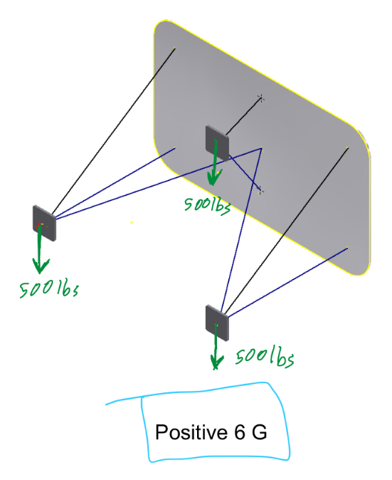
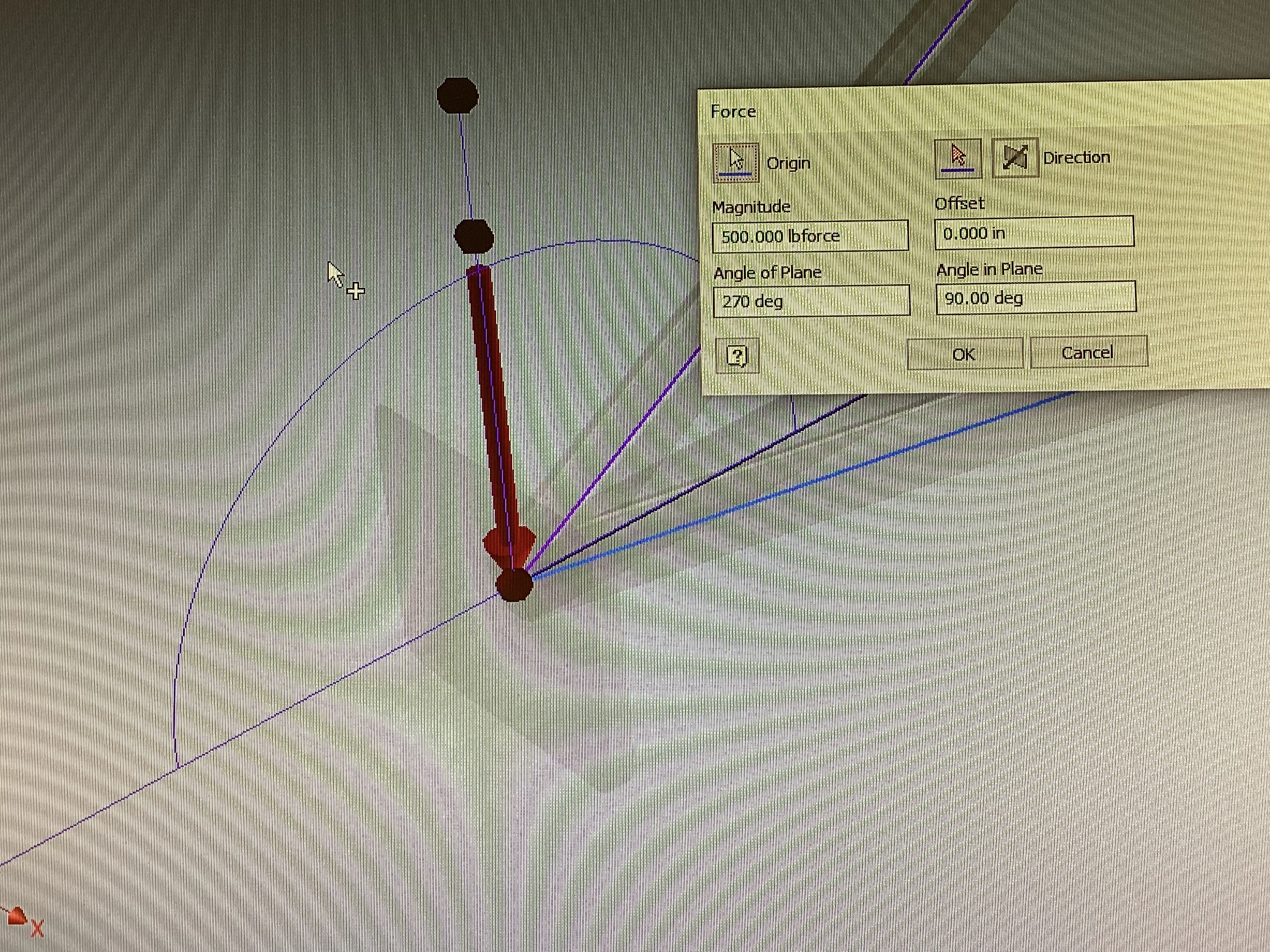
The Lycoming O-300 engine itself weighs 250 lbs at 1G. At -3G, the engine weighs -750 lbs, so each attachment point experiences a force of -250 lbs, or 250 lbs in the upward direction. However, at 6G the motor weighs 1500 lbs, so each attachment point experiences 500 lbs in the downward direction. To create a simulation in Autodesk Inventor, I added each force at each attachment point and then ran a static simulation.
Test Results
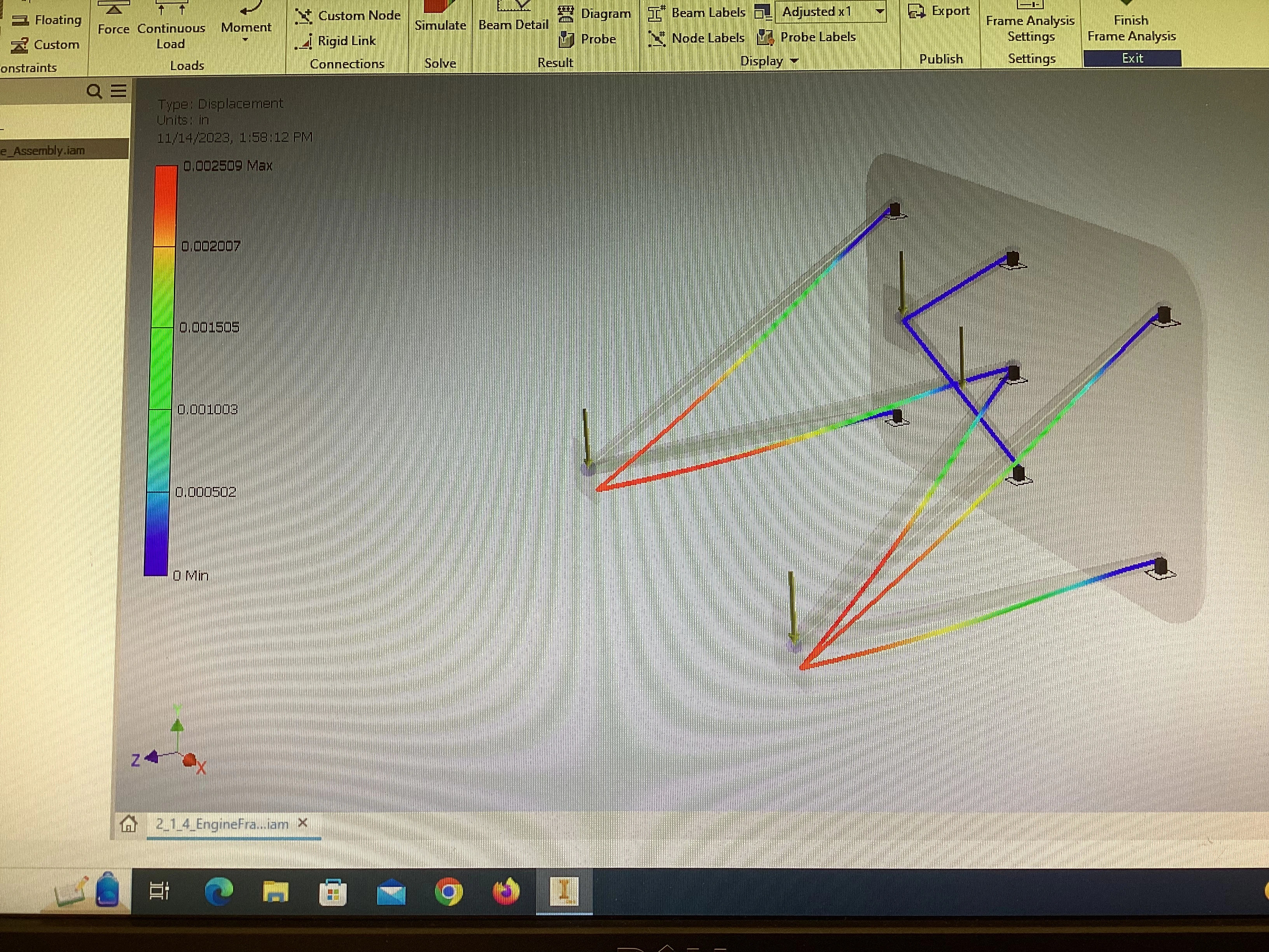
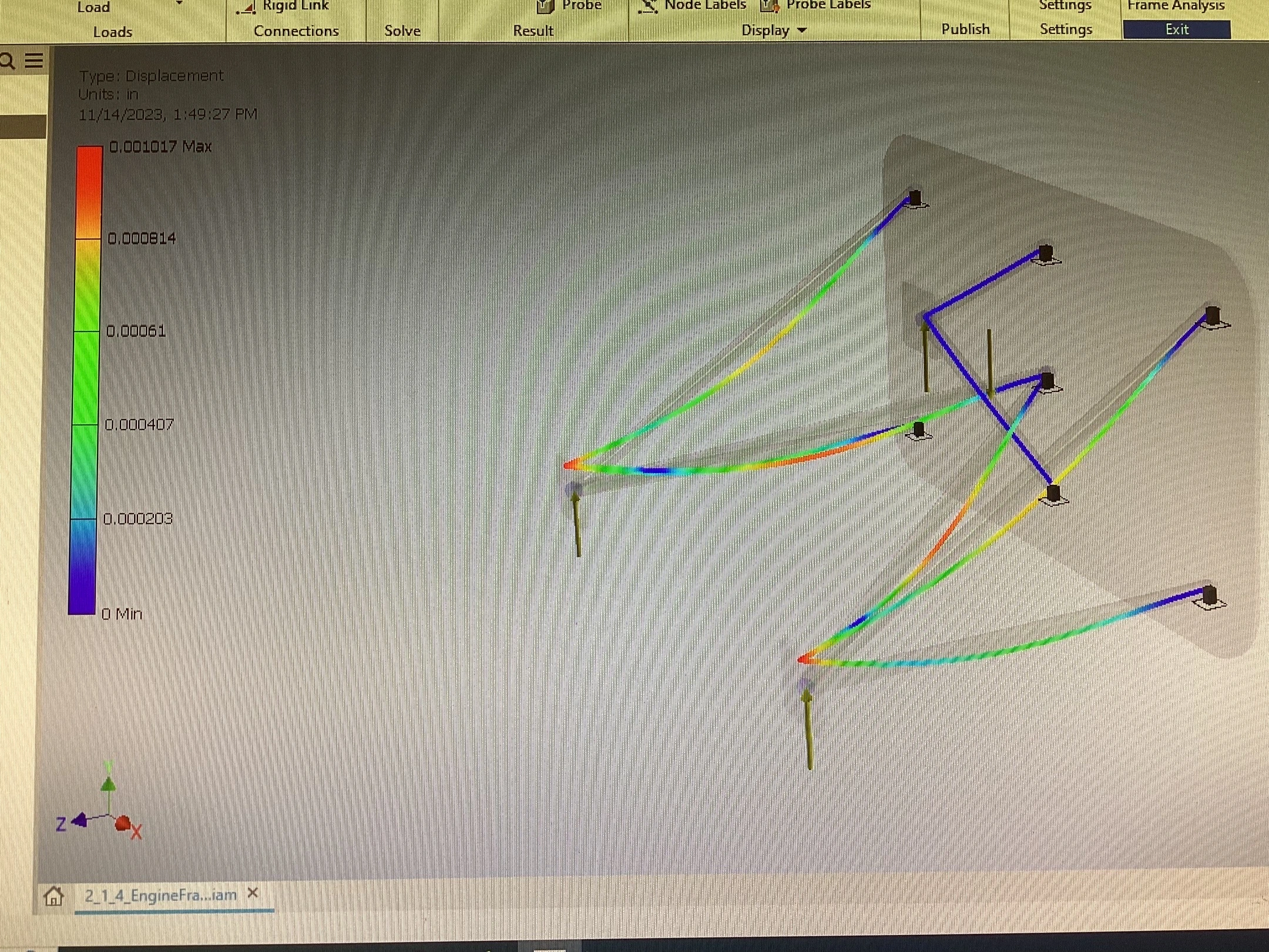
At -3G, the maximum deflection is 0.001017 inches. The max deflection occurs lTowards the center of the longest pipes (shown in red/orange). In contrast, at +6G, the maximum deflection is 0.002509 inches. This occurred at the attachment points of the engine mount. These attachment points would need to be both designed and welded very well to withstand the stresses in this situation.
Criteria Evaluation
This engine frame meets all criteria since intersections of steel pipes have been mitered, endpoints were trimmed, and the maximum deflections in extreme -3G and 6G maneuvers were miniscule. High strength low alloy steel was perfect for this situation.
Conclusion
During this project, I learned how to perform static analysis of maximum deflection on a design in Autodesk Inventor. In addition to engine frames, all other parts of an aircraft can be modelled and tested efficiently, accurately, precisely, and non-destructively. For example, wing torsion can be analyzed and minimized without comprimizing the safety of any person. This shows the great advantage of using CAD to simulate forces and create designs.